- Forums
- Product Forums
- General Purpose MicrocontrollersGeneral Purpose Microcontrollers
- i.MX Forumsi.MX Forums
- QorIQ Processing PlatformsQorIQ Processing Platforms
- Identification and SecurityIdentification and Security
- Power ManagementPower Management
- MCX Microcontrollers
- S32G
- S32K
- S32V
- MPC5xxx
- Other NXP Products
- Wireless Connectivity
- S12 / MagniV Microcontrollers
- Powertrain and Electrification Analog Drivers
- Sensors
- Vybrid Processors
- Digital Signal Controllers
- 8-bit Microcontrollers
- ColdFire/68K Microcontrollers and Processors
- PowerQUICC Processors
- OSBDM and TBDML
- S32M
-
- Solution Forums
- Software Forums
- MCUXpresso Software and ToolsMCUXpresso Software and Tools
- CodeWarriorCodeWarrior
- MQX Software SolutionsMQX Software Solutions
- Model-Based Design Toolbox (MBDT)Model-Based Design Toolbox (MBDT)
- FreeMASTER
- eIQ Machine Learning Software
- Embedded Software and Tools Clinic
- S32 SDK
- S32 Design Studio
- GUI Guider
- Zephyr Project
- Voice Technology
- Application Software Packs
- Secure Provisioning SDK (SPSDK)
- Processor Expert Software
- MCUXpresso Training Hub
-
- Topics
- Mobile Robotics - Drones and RoversMobile Robotics - Drones and Rovers
- NXP Training ContentNXP Training Content
- University ProgramsUniversity Programs
- Rapid IoT
- NXP Designs
- SafeAssure-Community
- OSS Security & Maintenance
- Using Our Community
-
- Cloud Lab Forums
-
- Knowledge Bases
- ARM Microcontrollers
- i.MX Processors
- Identification and Security
- Model-Based Design Toolbox (MBDT)
- QorIQ Processing Platforms
- S32 Automotive Processing Platform
- Wireless Connectivity
- CodeWarrior
- MCUXpresso Suite of Software and Tools
- MQX Software Solutions
-
- Home
- :
- i.MX フォーラム
- :
- i.MX RT クロスオーバーMCU
- :
- Setting FlexSPI root clock to slower clock rate: <= 30MHz
Setting FlexSPI root clock to slower clock rate: <= 30MHz
- RSS フィードを購読する
- トピックを新着としてマーク
- トピックを既読としてマーク
- このトピックを現在のユーザーにフロートします
- ブックマーク
- 購読
- ミュート
- 印刷用ページ
- 新着としてマーク
- ブックマーク
- 購読
- ミュート
- RSS フィードを購読する
- ハイライト
- 印刷
- 不適切なコンテンツを報告
Hi,
I am setting up FLEXSPI interface to communicate to FPGA chip which has been configured to run up to 30MHz.
I am referring to the SDK examples on how to setup the root clock for the FLEXSPI, as shown below:-
example: flexspi_nor_polling_transfer
const clock_usb_pll_config_t g_ccmConfigUsbPll = {.loopDivider = 0U};
CLOCK_InitUsb1Pll(&g_ccmConfigUsbPll);
// formula: USB1 PLL = 480MHz PLL3 => ((480MHz * 18) / fraction)
// Where, fraction = 24, so, USB1 PFD0 clock = (480MHz * 18) / 24 = 360MHz
CLOCK_InitUsb1Pfd(kCLOCK_Pfd0, 24);
// FLEXSPI_CLK_SEL
// 00 derive clock from semc_clk_root_pre
// 01 derive clock from pll3_sw_clk
// 10 derive clock from PLL2 PFD2
// 11 derive clock from PLL3 PFD0
CLOCK_SetMux(kCLOCK_FlexspiMux, 0x3);
// maximum FLEXSPI_PODF field value = 7 as it is a 3-bit field
// FLEXSPI_PODF = 2 => FLEXSPI root clock = 360MHz / 3 = 120MHz
// FLEXSPI_PODF = 7 => FLEXSPI root clock = 360MHz / 8 = 45MHz
CLOCK_SetDiv(kCLOCK_FlexspiDiv, 2);
As shown above, if FLEXSPI_CLK_SEL = PLL3 PFD0, even I set the FLEXSPI clock divider, FLEXSPI_PODF , to 7, the lowest possible FLEXSPI root clock = 45MHz.
Can you please suggest the best way to lower the FLEXSPI root clock freq to <= 30MHz? Should I set FLEXSPI_CLK_SEL = semc_clk_root_pre or something else?
Thank you!
Kind Regards,
Cindy
解決済! 解決策の投稿を見る。
- 新着としてマーク
- ブックマーク
- 購読
- ミュート
- RSS フィードを購読する
- ハイライト
- 印刷
- 不適切なコンテンツを報告
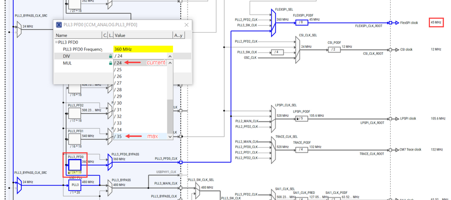
You should be able to lower the PLL3 PFD0 even further. You currently have it with a 24 divider, but it can be increased up to 35:
The resulting frequency should be 216/7 MHz.
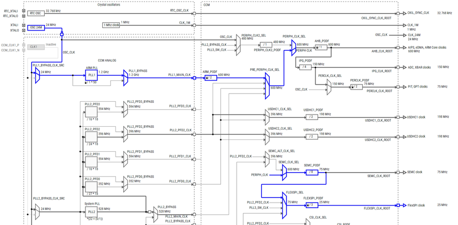
Alternatively, as you mention, by selecting the SEMC clock root clock as input for the FlexSPI clock divider, you should be able to get much lower frequencies, since the clock would be router after the SEMC clock divider, allowing you to control the signal with two dividers instead of one:
As you can see, from using the SEMC clock, I am able to output a 25 MHz signal.
Hope this helps,
Edwin.

