
- Forums
- Product Forums
- General Purpose MicrocontrollersGeneral Purpose Microcontrollers
- i.MX Forumsi.MX Forums
- QorIQ Processing PlatformsQorIQ Processing Platforms
- Identification and SecurityIdentification and Security
- Power ManagementPower Management
- Wireless ConnectivityWireless Connectivity
- RFID / NFCRFID / NFC
- Advanced AnalogAdvanced Analog
- Neural Processing UnitsNeural Processing Units
- MCX Microcontrollers
- S32G
- S32K
- S32V
- MPC5xxx
- Other NXP Products
- S12 / MagniV Microcontrollers
- Powertrain and Electrification Analog Drivers
- Sensors
- Vybrid Processors
- Digital Signal Controllers
- 8-bit Microcontrollers
- ColdFire/68K Microcontrollers and Processors
- PowerQUICC Processors
- OSBDM and TBDML
- S32M
- S32Z/E
-
- Solution Forums
- Software Forums
- MCUXpresso Software and ToolsMCUXpresso Software and Tools
- CodeWarriorCodeWarrior
- MQX Software SolutionsMQX Software Solutions
- Model-Based Design Toolbox (MBDT)Model-Based Design Toolbox (MBDT)
- FreeMASTER
- eIQ Machine Learning Software
- Embedded Software and Tools Clinic
- S32 SDK
- S32 Design Studio
- GUI Guider
- Zephyr Project
- Voice Technology
- Application Software Packs
- Secure Provisioning SDK (SPSDK)
- Processor Expert Software
- Generative AI & LLMs
-
- Topics
- Mobile Robotics - Drones and RoversMobile Robotics - Drones and Rovers
- NXP Training ContentNXP Training Content
- University ProgramsUniversity Programs
- Rapid IoT
- NXP Designs
- SafeAssure-Community
- OSS Security & Maintenance
- Using Our Community
-
- Cloud Lab Forums
-
- Knowledge Bases
- ARM Microcontrollers
- i.MX Processors
- Identification and Security
- Model-Based Design Toolbox (MBDT)
- QorIQ Processing Platforms
- S32 Automotive Processing Platform
- Wireless Connectivity
- CodeWarrior
- MCUXpresso Suite of Software and Tools
- MQX Software Solutions
- RFID / NFC
- Advanced Analog
- Neural Processing Units
-
- NXP Tech Blogs
- Home
- :
- i.MX Forums
- :
- i.MX Processors
- :
- Re: i.MX8M Mini pull-down resistor on boot pins
i.MX8M Mini pull-down resistor on boot pins
- Subscribe to RSS Feed
- Mark Topic as New
- Mark Topic as Read
- Float this Topic for Current User
- Bookmark
- Subscribe
- Mute
- Printer Friendly Page

- Mark as New
- Bookmark
- Subscribe
- Mute
- Subscribe to RSS Feed
- Permalink
- Report Inappropriate Content
Hi everyone,
I am starting working with i.MX8M Mini processor, for a custom SOM. I am having trouble understanding the behavior of pull-down resistors on GPIO related to the boot circuit.
Does this
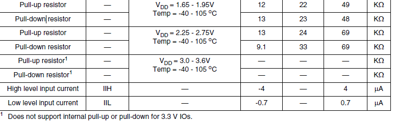
mean that if I power the NVCC_JTAG and NVCC_SAI1 pins (both related to the boot pins) with 3.3V, I won't have internal pull-up/down resistors on the pins that control the boot operation mode?
Thank you in advance,
Lorenzo
Solved! Go to Solution.

 AldoG
AldoG
- Mark as New
- Bookmark
- Subscribe
- Mute
- Subscribe to RSS Feed
- Permalink
- Report Inappropriate Content
Hello,
Yes you're correct you'll have a voltage partition between 4.7K pull-up and internal pull-down, only if no external pull down is added, this pull-down resistor is typically 20K (3.3V IOs) which by errata e50080 changes over time from 20k upwards of 92k ohm.
From errata document IMX8MM_0N87W:
There is a degradation of the internal IO pullup/pulldown capability when certain IO pads are continuously driven in a 3.3V operating condition which limits the pads pull up/down ability. The impedance of these pads changes over time from 20K to upwards of 92K ohm.
You may find the errata document here:
i.MX 8M Mini Mask Set Errata for Mask 0N87W
Hope this helps,
Best regards,
Aldo.
AldoG
- Mark as New
- Bookmark
- Subscribe
- Mute
- Subscribe to RSS Feed
- Permalink
- Report Inappropriate Content
Hello,
As per ERRATA50080 IO internal pull up/down is not supported in 3.3V mode, must disable the internal pull up/down via software and use external pull up/down resistors instead.
All IO pin groups are impacted except for XTAL, DDR, PCI, USB and MIPI PHY IO's.
Hope this helps,
Best regards,
Aldo.
-------------------------------------------------------------------------------
Note:
- If this post answers your question, please click the "Mark Correct" button. Thank you!
- We are following threads for 7 weeks after the last post, later replies are ignored
Please open a new thread and refer to the closed one, if you have a related question at a later point in time.
-------------------------------------------------------------------------------
- Mark as New
- Bookmark
- Subscribe
- Mute
- Subscribe to RSS Feed
- Permalink
- Report Inappropriate Content
Hi,
Thanks for your answer.
However, I still have a doubt about the boot conditions, when the software isn't started yet. If during the boot, the internal pull-down resistors aren't disabled yet, does this situation
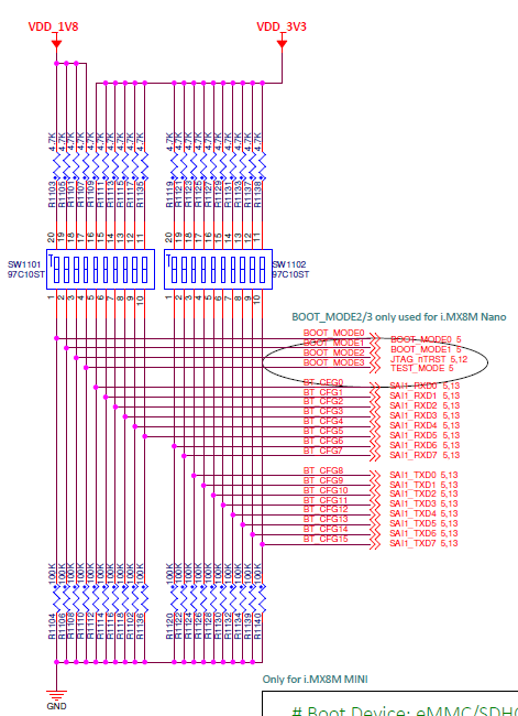
mean that I'll have a voltage partition between the pull-up resistors 4.7k and the internal pull-down resistors? If I need a high logic state on some of those pins, maybe 4.7k is too high considering the minimum value of the internal pull-down resistors (9.1k for 2.25V < Vdd < 2.75V). This schematic is taken from the NXP evaluation board.
Also, from this table
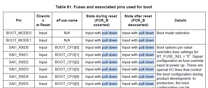
it seems that right after the reset, the pins are pulled down.
I assume that the external pull-up/down resistors used for the evaluation board work, but by reading the datasheet it seems that if the internal pull-down resistor approaches its lower limit indicated in the datasheet, then the voltage level on high logic state during the boot could be below the threshold.
Could you clarify this please?
Thank you in advance,
Lorenzo
AldoG
- Mark as New
- Bookmark
- Subscribe
- Mute
- Subscribe to RSS Feed
- Permalink
- Report Inappropriate Content
Hello,
Yes you're correct you'll have a voltage partition between 4.7K pull-up and internal pull-down, only if no external pull down is added, this pull-down resistor is typically 20K (3.3V IOs) which by errata e50080 changes over time from 20k upwards of 92k ohm.
From errata document IMX8MM_0N87W:
There is a degradation of the internal IO pullup/pulldown capability when certain IO pads are continuously driven in a 3.3V operating condition which limits the pads pull up/down ability. The impedance of these pads changes over time from 20K to upwards of 92K ohm.
You may find the errata document here:
i.MX 8M Mini Mask Set Errata for Mask 0N87W
Hope this helps,
Best regards,
Aldo.
