
- Forums
- Product Forums
- General Purpose MicrocontrollersGeneral Purpose Microcontrollers
- i.MX Forumsi.MX Forums
- QorIQ Processing PlatformsQorIQ Processing Platforms
- Identification and SecurityIdentification and Security
- Power ManagementPower Management
- Wireless ConnectivityWireless Connectivity
- RFID / NFCRFID / NFC
- Advanced AnalogAdvanced Analog
- Neural Processing UnitsNeural Processing Units
- MCX Microcontrollers
- S32G
- S32K
- S32V
- MPC5xxx
- Other NXP Products
- S12 / MagniV Microcontrollers
- Powertrain and Electrification Analog Drivers
- Sensors
- Vybrid Processors
- Digital Signal Controllers
- 8-bit Microcontrollers
- ColdFire/68K Microcontrollers and Processors
- PowerQUICC Processors
- OSBDM and TBDML
- S32M
- S32Z/E
-
- Solution Forums
- Software Forums
- MCUXpresso Software and ToolsMCUXpresso Software and Tools
- CodeWarriorCodeWarrior
- MQX Software SolutionsMQX Software Solutions
- Model-Based Design Toolbox (MBDT)Model-Based Design Toolbox (MBDT)
- FreeMASTER
- eIQ Machine Learning Software
- Embedded Software and Tools Clinic
- S32 SDK
- S32 Design Studio
- GUI Guider
- Zephyr Project
- Voice Technology
- Application Software Packs
- Secure Provisioning SDK (SPSDK)
- Processor Expert Software
- Generative AI & LLMs
-
- Topics
- Mobile Robotics - Drones and RoversMobile Robotics - Drones and Rovers
- NXP Training ContentNXP Training Content
- University ProgramsUniversity Programs
- Rapid IoT
- NXP Designs
- SafeAssure-Community
- OSS Security & Maintenance
- Using Our Community
-
- Cloud Lab Forums
-
- Knowledge Bases
- ARM Microcontrollers
- i.MX Processors
- Identification and Security
- Model-Based Design Toolbox (MBDT)
- QorIQ Processing Platforms
- S32 Automotive Processing Platform
- Wireless Connectivity
- CodeWarrior
- MCUXpresso Suite of Software and Tools
- MQX Software Solutions
- RFID / NFC
- Advanced Analog
- Neural Processing Units
-
- NXP Tech Blogs
- Home
- :
- i.MX Forums
- :
- i.MX Processors
- :
- Re: PF Series Programmer not being detected correctly
PF Series Programmer not being detected correctly
- Subscribe to RSS Feed
- Mark Topic as New
- Mark Topic as Read
- Float this Topic for Current User
- Bookmark
- Subscribe
- Mute
- Printer Friendly Page
PF Series Programmer not being detected correctly

- Mark as New
- Bookmark
- Subscribe
- Mute
- Subscribe to RSS Feed
- Permalink
- Report Inappropriate Content
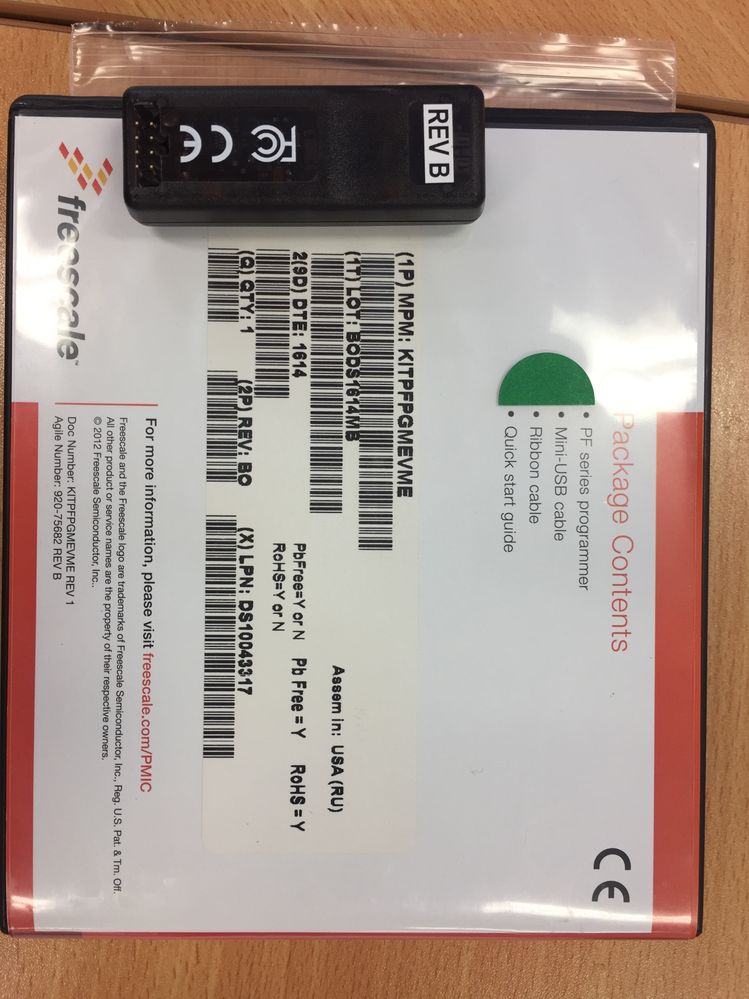
We have just purchased a PF Series Programmer ( KITPFPGMEVME ) with the intention of programming a custom configuration into a PF0100 PMIC that's been placed onto a new i.MX6 design of ours.
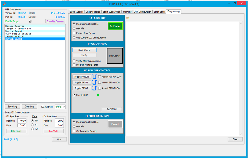
The issue we're having is that when we connect the programmer, the USB programmer enumerates with the Part ID 0x00F5 for the PF0100 EVK Target, which disables the OTP functions of the GUI. The PF0100 PMIC on our board is being detected correctly by the programmer, but we've been unable to figure out how to perform the OTP, as the PROGRAM button is disabled.
We are assuming the programmer should be enumerating with the Part ID 0x0050 and target PF-Programmer.
Any suggestions ?
- Mark as New
- Bookmark
- Subscribe
- Mute
- Subscribe to RSS Feed
- Permalink
- Report Inappropriate Content
Hi Jose,
Thanks for the response.
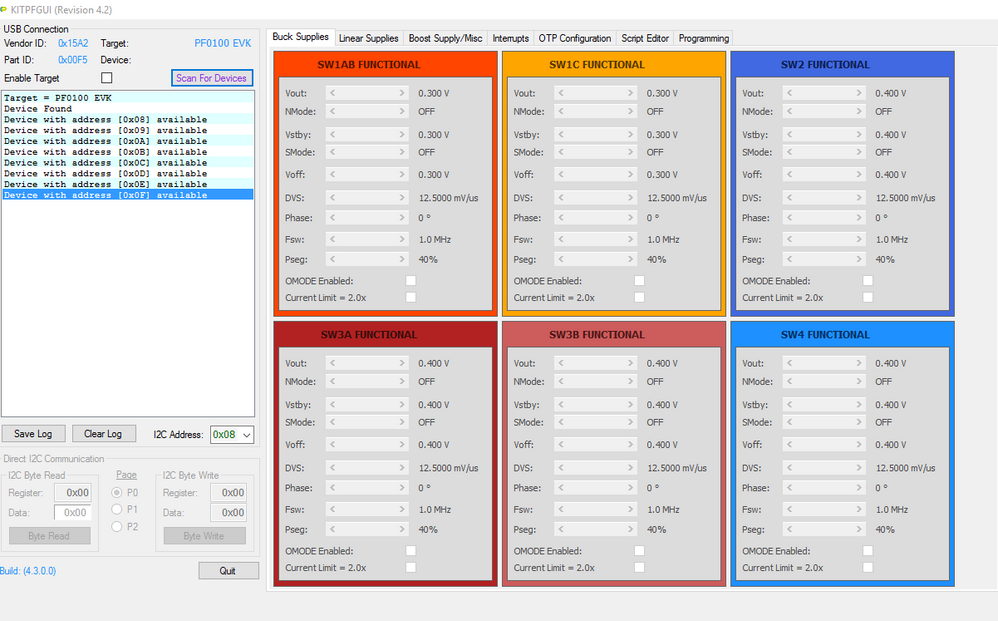
We've now tried the latest software on a number of windows boxes ( Windows 7 -> 10 ), and each time the programmer is coming up as PID 0x00F5.
We do not own the PF0100EVK kit, and this is the only programmer/dev kit we are attaching to the PC.
Any other suggestions ? Is it possible the programmer has been shipped with the incorrect firmware/USB configuration ?
Cheers,
Steve VDW.

 reyes
reyes
- Mark as New
- Bookmark
- Subscribe
- Mute
- Subscribe to RSS Feed
- Permalink
- Report Inappropriate Content
Hi Steve,
If I understand properly, the PF-Programmer is connected to a custom design, right?
If this is the case, make sure that the I2C interface pull-up resistors are placed and functioning properly, these resistors should be near the SCL and SDA pins on the target PMIC. If not, the GUI will read all 0xFFs, and give you erroneous information.
The pull-up resistors, VDDIO, and VIN require 3.3V to function properly. There is a 3.3V LDO output on the PF-Programmer dongle that can supply ~250mA of current. When the 8.5V VPGM boost is enabled, it shares the USB VBUS current with the LDO. During programming the VPGM boost supply needs ~280mA peak, so the total current available to the 3.3V LDO will be reduced.
If you are trying to use the PF-Programmer to supply 3.3V VIN to your target board, it may not be enough, since the PMIC outputs may be loaded. If you are powering your board externally (3.3V Bench Supply), then you should connect this voltage to VDDIO to power the I2C interface. Then just make sure that the SCL, SDA, GND, and VPGM signals from the PF-Programmer is connected to your target board.
If you persist in seeing the PF0100 EVK as your Target after this, you may have received a bad PF-Programmer dongle.
Have a great day,
Jose
-----------------------------------------------------------------------------------------------------------------------
Note: If this post answers your question, please click the Correct Answer button. Thank you!
-----------------------------------------------------------------------------------------------------------------------
reyes
- Mark as New
- Bookmark
- Subscribe
- Mute
- Subscribe to RSS Feed
- Permalink
- Report Inappropriate Content
Hi,
First, let’s upgrade you to the latest version of the GUI 4.3.0.0 (find it attached).
Please uninstall completely previous versions of the GUI, then install this new version of the GUI.
Now to the issue. On PF0100/0200 parts, we use the USB PID to determine which hardware is attached:
PID = 0x0050 à PF-Programmer
PID = 0x00F5 à PF0100 EVK
PID = 0x00F6 à PF0200 EVK
If you are seeing a PID of 0x00F5 even though you are connecting a PF-Programmer dongle, then your PC is somehow not releasing the USB device. If you are trying to connect to some other USB-to-I2C interface device, make sure that it presents a VID: 0x15A2 and PID: 0x0050. Otherwise the GUI will not enable the [PROGRAM] button.
Have a great day,
Jose
-----------------------------------------------------------------------------------------------------------------------
Note: If this post answers your question, please click the Correct Answer button. Thank you!
-----------------------------------------------------------------------------------------------------------------------
