
- Forums
- Product Forums
- General Purpose MicrocontrollersGeneral Purpose Microcontrollers
- i.MX Forumsi.MX Forums
- QorIQ Processing PlatformsQorIQ Processing Platforms
- Identification and SecurityIdentification and Security
- Power ManagementPower Management
- Wireless ConnectivityWireless Connectivity
- RFID / NFCRFID / NFC
- Advanced AnalogAdvanced Analog
- Neural Processing UnitsNeural Processing Units
- MCX Microcontrollers
- S32G
- S32K
- S32V
- MPC5xxx
- Other NXP Products
- S12 / MagniV Microcontrollers
- Powertrain and Electrification Analog Drivers
- Sensors
- Vybrid Processors
- Digital Signal Controllers
- 8-bit Microcontrollers
- ColdFire/68K Microcontrollers and Processors
- PowerQUICC Processors
- OSBDM and TBDML
- S32M
- S32Z/E
-
- Solution Forums
- Software Forums
- MCUXpresso Software and ToolsMCUXpresso Software and Tools
- CodeWarriorCodeWarrior
- MQX Software SolutionsMQX Software Solutions
- Model-Based Design Toolbox (MBDT)Model-Based Design Toolbox (MBDT)
- FreeMASTER
- eIQ Machine Learning Software
- Embedded Software and Tools Clinic
- S32 SDK
- S32 Design Studio
- GUI Guider
- Zephyr Project
- Voice Technology
- Application Software Packs
- Secure Provisioning SDK (SPSDK)
- Processor Expert Software
- Generative AI & LLMs
-
- Topics
- Mobile Robotics - Drones and RoversMobile Robotics - Drones and Rovers
- NXP Training ContentNXP Training Content
- University ProgramsUniversity Programs
- Rapid IoT
- NXP Designs
- SafeAssure-Community
- OSS Security & Maintenance
- Using Our Community
-
- Cloud Lab Forums
-
- Knowledge Bases
- ARM Microcontrollers
- i.MX Processors
- Identification and Security
- Model-Based Design Toolbox (MBDT)
- QorIQ Processing Platforms
- S32 Automotive Processing Platform
- Wireless Connectivity
- CodeWarrior
- MCUXpresso Suite of Software and Tools
- MQX Software Solutions
- RFID / NFC
- Advanced Analog
- Neural Processing Units
-
- NXP Tech Blogs
- Home
- :
- i.MX Forums
- :
- i.MX Processors
- :
- Re: MX6ULL OTG not working
MX6ULL OTG not working
- Subscribe to RSS Feed
- Mark Topic as New
- Mark Topic as Read
- Float this Topic for Current User
- Bookmark
- Subscribe
- Mute
- Printer Friendly Page

- Mark as New
- Bookmark
- Subscribe
- Mute
- Subscribe to RSS Feed
- Permalink
- Report Inappropriate Content
Hi,
We are using customized i.MX6ULL board. We are using OTG1 interface as serial download interface and also we are trying to connect OTG cable to that port. We are having one power switch to enable the 5V to uUSB port for which the enable signal is coming from OTG1_PWR signal. At first when we checked the dts file there was no muxing option for the OTG1_PWR and OTG1_OC pin. At this configuration when we changed the status of the OTG1_PWR signal to logic HIGH via the gpio application in U-boot and then boot the board, we are able to detect the pen drive connected to the uUSB port via the OTG cable. When we had muxed both the pins in Kernel and U-boot dts files, the OTG1_PWR signal was always logic HIGH and we can't control that signal via the gpio application in U-boot. After the board boots up also the, even though uUSB is getting 5V power supply the USB devices connected to the port is not getting detected at all.
So is there a way to specify in the dts file the logic levels for that signal like ACTIVE_HIGH/LOW?
Thanks,
Ranjith
Solved! Go to Solution.

 weidong_sun
- Mark as New
- Bookmark
- Subscribe
- Mute
- Subscribe to RSS Feed
- Permalink
- Report Inappropriate Content
Hello Ranjith,
If USB OTG1 works in device mode, USB_OTG1_ID should be pulled up to High(here is 3.3V) via a 4.7K/10K resistor. USB_OTG1_VBUS power comes from USB_VBUS on mircro USB Connector, which means USB OTG1 VBUS is supplied by external 5V(coming from PC USB when it is connected to PC USB HOST).
If USB OTG1 works in Host mode, USB_OTG1_ID pin should be pulled down to LOW via a resistor(for example, 2.2k). At this time, USB OTG1 PWR should output HIGH to enable USB OTG1 power to supply 5V to USB OTG1 VUBS and USB VBUS on USB HOST Connector(USB TYPE-A-F).
OK, try the following code:
......
regulators {
compatible = "simple-bus";
#address-cells = <1>;
#size-cells = <0>;
......
reg_gpio_dvfs: regulator-gpio {
compatible = "regulator-gpio";
pinctrl-names = "default";
pinctrl-0 = <&pinctrl_dvfs>;
regulator-min-microvolt = <1300000>;
regulator-max-microvolt = <1400000>;
regulator-name = "gpio_dvfs";
regulator-type = "voltage";
gpios = <&gpio5 3 GPIO_ACTIVE_HIGH>;
states = <1300000 0x1 1400000 0x0>;
};
/* add the node to regulator. */
reg_usb_otg1_vbus: regulator@2 {
compatible = "regulator-fixed";
reg = <2>;
regulator-name = "usb_otg_vbus";
regulator-min-microvolt = <5000000>;
regulator-max-microvolt = <5000000>;
gpio = <&gpio1 4 0>;
enable-active-high;
};
... ...
}
pinctrl_hog_1: hoggrp-1 {
fsl,pins = <
MX6UL_PAD_UART1_RTS_B__GPIO1_IO19 0x17059 /* SD1 CD */
MX6UL_PAD_GPIO1_IO05__USDHC1_VSELECT 0x17059 /* SD1 VSELECT */
MX6UL_PAD_GPIO1_IO09__GPIO1_IO09 0x17059 /* SD1 RESET */
MX6UL_PAD_GPIO1_IO04__GPIO1_IO04 0x17059
>;
};
pinctrl_usb_otg1_id: usbotg1idgrp {
fsl,pins = <
MX6UL_PAD_GPIO1_IO00__ANATOP_OTG1_ID 0x17059 /* check if it has been in dts, if not , add it.*/
>;
};
&usbotg1 {
vbus-supply = <®_usb_otg1_vbus>; /* add power control */
pinctrl-names = "default";
pinctrl-0 = <&pinctrl_usb_otg1_id>;
dr_mode = "otg";
srp-disable;
hnp-disable;
adp-disable;
status = "okay";
};
try it, please!
Have a nice day!
Weidong
weidong_sun
- Mark as New
- Bookmark
- Subscribe
- Mute
- Subscribe to RSS Feed
- Permalink
- Report Inappropriate Content
Hello Ranjith,
Due to no customer's schematic, I have no way to know how customer uses the pin GPIO1_IO04. I only refer to IMX6ULL-EVK's usage for the pin, GPIO1_IO04 can be multiplexed as USB_OTG1_PWR or GPIO1_IO04, see imx6ul-pinfunc.h file:
MX6UL_PAD_GPIO1_IO04__USB_OTG1_PWR
MX6UL_PAD_GPIO1_IO04__GPIO1_IO04
On imx6ull-evk, GPIO1_IO04 pin is used for touch screen control, which means TS driver is using it. so probably you can't opreate it on application level.
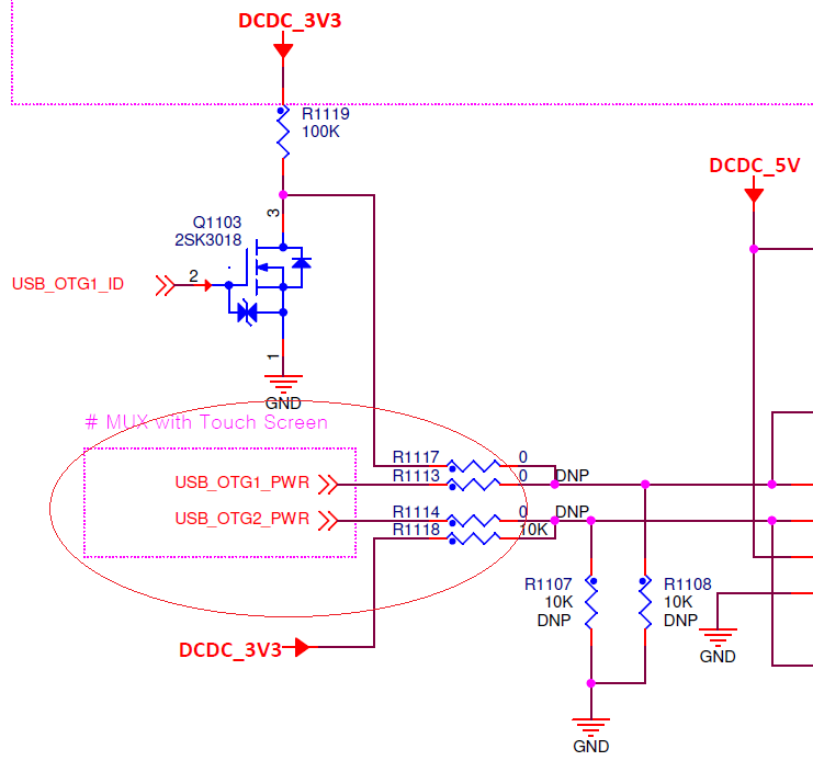
From EVK schematic, USB OTG1 Power is controlled by USB_OTG1_ID's level, So by default USB_OTG1_PWR signal is not used.
If the pin is used to control USB OTG1 power on your board, you should multiplex it to be USB_OTG1_PWR, but not GPIO.
Hope above information is helpful for you.
Have a nice day!
B.R,
Weidong
- Mark as New
- Bookmark
- Subscribe
- Mute
- Subscribe to RSS Feed
- Permalink
- Report Inappropriate Content
Hi Wigros,
I have disabled the TSC in dts file and multiplexed the the GPIO1_IO04 pin to be USB_OTG1_PWR signal but making this change also didn't made the OTG to work. The other query is like how to change the detection level from ACTIVE_LOW to ACTIVE_HIGH for both OTG1_PWR and OTG1_OC signals in dts file?
Thanks,
Ranjith
weidong_sun
- Mark as New
- Bookmark
- Subscribe
- Mute
- Subscribe to RSS Feed
- Permalink
- Report Inappropriate Content
Hello Ranjith,
At least , USB OTG1 can work in device mode ,so MFG tools or uuu can flash images into eMMC or SD card.
Can you program it normally?
weidong
- Mark as New
- Bookmark
- Subscribe
- Mute
- Subscribe to RSS Feed
- Permalink
- Report Inappropriate Content
Hi Wigros,
Yes we can flash the eMMC or SD card via UUU tool perfectly. The only problem is that OTG devices is not getting detected in OTG1 port. Is there a way to change the detection level for those 2 signals which I had mentioned earlier to ACTIVE_HIGH from ACTIVE_LOW in the dts file?
Thanks,
Ranjith.
weidong_sun
- Mark as New
- Bookmark
- Subscribe
- Mute
- Subscribe to RSS Feed
- Permalink
- Report Inappropriate Content
Hello Ranjith,
If USB OTG1 works in device mode, USB_OTG1_ID should be pulled up to High(here is 3.3V) via a 4.7K/10K resistor. USB_OTG1_VBUS power comes from USB_VBUS on mircro USB Connector, which means USB OTG1 VBUS is supplied by external 5V(coming from PC USB when it is connected to PC USB HOST).
If USB OTG1 works in Host mode, USB_OTG1_ID pin should be pulled down to LOW via a resistor(for example, 2.2k). At this time, USB OTG1 PWR should output HIGH to enable USB OTG1 power to supply 5V to USB OTG1 VUBS and USB VBUS on USB HOST Connector(USB TYPE-A-F).
OK, try the following code:
......
regulators {
compatible = "simple-bus";
#address-cells = <1>;
#size-cells = <0>;
......
reg_gpio_dvfs: regulator-gpio {
compatible = "regulator-gpio";
pinctrl-names = "default";
pinctrl-0 = <&pinctrl_dvfs>;
regulator-min-microvolt = <1300000>;
regulator-max-microvolt = <1400000>;
regulator-name = "gpio_dvfs";
regulator-type = "voltage";
gpios = <&gpio5 3 GPIO_ACTIVE_HIGH>;
states = <1300000 0x1 1400000 0x0>;
};
/* add the node to regulator. */
reg_usb_otg1_vbus: regulator@2 {
compatible = "regulator-fixed";
reg = <2>;
regulator-name = "usb_otg_vbus";
regulator-min-microvolt = <5000000>;
regulator-max-microvolt = <5000000>;
gpio = <&gpio1 4 0>;
enable-active-high;
};
... ...
}
pinctrl_hog_1: hoggrp-1 {
fsl,pins = <
MX6UL_PAD_UART1_RTS_B__GPIO1_IO19 0x17059 /* SD1 CD */
MX6UL_PAD_GPIO1_IO05__USDHC1_VSELECT 0x17059 /* SD1 VSELECT */
MX6UL_PAD_GPIO1_IO09__GPIO1_IO09 0x17059 /* SD1 RESET */
MX6UL_PAD_GPIO1_IO04__GPIO1_IO04 0x17059
>;
};
pinctrl_usb_otg1_id: usbotg1idgrp {
fsl,pins = <
MX6UL_PAD_GPIO1_IO00__ANATOP_OTG1_ID 0x17059 /* check if it has been in dts, if not , add it.*/
>;
};
&usbotg1 {
vbus-supply = <®_usb_otg1_vbus>; /* add power control */
pinctrl-names = "default";
pinctrl-0 = <&pinctrl_usb_otg1_id>;
dr_mode = "otg";
srp-disable;
hnp-disable;
adp-disable;
status = "okay";
};
try it, please!
Have a nice day!
Weidong
- Mark as New
- Bookmark
- Subscribe
- Mute
- Subscribe to RSS Feed
- Permalink
- Report Inappropriate Content
Hi Wigros,
After the including the changes told by you in our dts file USB devices are getting detected in USB_OTG1 port when connected through OTG cable. Thanks for your help.
With regards,
Ranjith.
