- Forums
- Product Forums
- General Purpose MicrocontrollersGeneral Purpose Microcontrollers
- i.MX Forumsi.MX Forums
- QorIQ Processing PlatformsQorIQ Processing Platforms
- Identification and SecurityIdentification and Security
- Power ManagementPower Management
- MCX Microcontrollers
- S32G
- S32K
- S32V
- MPC5xxx
- Other NXP Products
- Wireless Connectivity
- S12 / MagniV Microcontrollers
- Powertrain and Electrification Analog Drivers
- Sensors
- Vybrid Processors
- Digital Signal Controllers
- 8-bit Microcontrollers
- ColdFire/68K Microcontrollers and Processors
- PowerQUICC Processors
- OSBDM and TBDML
- S32M
-
- Solution Forums
- Software Forums
- MCUXpresso Software and ToolsMCUXpresso Software and Tools
- CodeWarriorCodeWarrior
- MQX Software SolutionsMQX Software Solutions
- Model-Based Design Toolbox (MBDT)Model-Based Design Toolbox (MBDT)
- FreeMASTER
- eIQ Machine Learning Software
- Embedded Software and Tools Clinic
- S32 SDK
- S32 Design Studio
- GUI Guider
- Zephyr Project
- Voice Technology
- Application Software Packs
- Secure Provisioning SDK (SPSDK)
- Processor Expert Software
- MCUXpresso Training Hub
-
- Topics
- Mobile Robotics - Drones and RoversMobile Robotics - Drones and Rovers
- NXP Training ContentNXP Training Content
- University ProgramsUniversity Programs
- Rapid IoT
- NXP Designs
- SafeAssure-Community
- OSS Security & Maintenance
- Using Our Community
-
- Cloud Lab Forums
-
- Knowledge Bases
- ARM Microcontrollers
- i.MX Processors
- Identification and Security
- Model-Based Design Toolbox (MBDT)
- QorIQ Processing Platforms
- S32 Automotive Processing Platform
- Wireless Connectivity
- CodeWarrior
- MCUXpresso Suite of Software and Tools
- MQX Software Solutions
-
Hi,
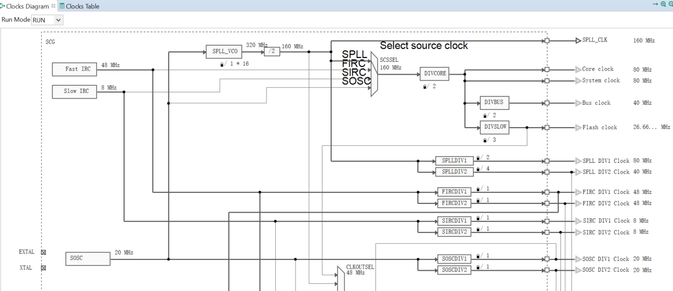
I want to clock the core (CORE_CLK, SYS_CLK, BUS_CLK, FLASH_CLK) by using the PLL clock as source. My prefered clock frequencies are the following:
- CORE_CLK - 80MHz
- SYS_CLK - 80MHz
- BUS_CLK - 40MHz
- FLASH_CLK - 26.67MHz
Please see below my clock config struct:
clock_manager_user_config_t clockMan1_InitConfig0 = {
/*! @brief Configuration of SIRC */
.scgConfig =
{
.sircConfig =
{
.initialize = true, /*!< Initialize */
/* SIRCCSR */
.enableInStop = false, /*!< SIRCSTEN */
.enableInLowPower = true, /*!< SIRCLPEN */
.locked = false, /*!< LK */
/* SIRCCFG */
.range = SCG_SIRC_RANGE_HIGH, /*!< RANGE - High range (8 MHz) */
/* SIRCDIV */
.div1 = SCG_ASYNC_CLOCK_DIV_BY_1, /*!< SIRCDIV1 */
.div2 = SCG_ASYNC_CLOCK_DIV_BY_1, /*!< SIRCDIV2 */
},
.fircConfig =
{
.initialize = true, /*!< Initialize */
/* FIRCCSR */
.regulator = true, /*!< FIRCREGOFF */
.locked = false, /*!< LK */
/* FIRCCFG */
.range = SCG_FIRC_RANGE_48M, /*!< RANGE */
/* FIRCDIV */
.div1 = SCG_ASYNC_CLOCK_DIV_BY_1, /*!< FIRCDIV1 */
.div2 = SCG_ASYNC_CLOCK_DIV_BY_1, /*!< FIRCDIV2 */
},
.rtcConfig =
{
.initialize = true, /*!< Initialize */
.rtcClkInFreq = 0U, /*!< RTC_CLKIN */
},
.soscConfig =
{
.initialize = true, /*!< Initialize */
.freq = 20000000U, /*!< Frequency */
/* SOSCCSR */
.monitorMode = SCG_SOSC_MONITOR_DISABLE, /*!< SOSCCM */
.locked = false, /*!< LK */
/* SOSCCFG */
.extRef = SCG_SOSC_REF_OSC, /*!< EREFS */
.gain = SCG_SOSC_GAIN_LOW, /*!< HGO */
.range = SCG_SOSC_RANGE_HIGH, /*!< RANGE */
/* SOSCDIV */
.div1 = SCG_ASYNC_CLOCK_DIV_BY_1, /*!< SOSCDIV1 */
.div2 = SCG_ASYNC_CLOCK_DIV_BY_1, /*!< SOSCDIV2 */
},
.spllConfig =
{
.initialize = true, /*!< Initialize */
/* SPLLCSR */
.monitorMode = SCG_SPLL_MONITOR_DISABLE, /*!< SPLLCM */
.locked = false, /*!< LK */
/* SPLLCFG */
.prediv = (uint8_t)SCG_SPLL_CLOCK_PREDIV_BY_2, /*!< PREDIV */
.mult = (uint8_t)SCG_SPLL_CLOCK_MULTIPLY_BY_32, /*!< MULT */
.src=0U, /*!< SOURCE */
/* SPLLDIV */
.div1 = SCG_ASYNC_CLOCK_DIV_BY_2, /*!< SPLLDIV1 @ 80MHz */
.div2 = SCG_ASYNC_CLOCK_DIV_BY_4, /*!< SPLLDIV2 @ 40MHz */
},
.clockOutConfig =
{
.initialize = true, /*!< Initialize */
.source = SCG_CLOCKOUT_SRC_SIRC, /*!< SCG CLKOUTSEL */
},
.clockModeConfig =
{
.initialize = true, /*!< Initialize */
.rccrConfig = /*!< RCCR - Run Clock Control Register */
{
.src=SCG_SYSTEM_CLOCK_SRC_SYS_PLL, /*!< SCS SPLL @ 160MHz */
.divCore = SCG_SYSTEM_CLOCK_DIV_BY_2, /*!< DIVCORE Core @ 80MHz */
.divBus = SCG_SYSTEM_CLOCK_DIV_BY_2, /*!< DIVBUS Bus @ 40Mhz */
.divSlow = SCG_SYSTEM_CLOCK_DIV_BY_4, /*!< DIVSLOW Flash @ 26.67MHz */
},
.vccrConfig = /*!< VCCR - VLPR Clock Control Register */
{
.src=SCG_SYSTEM_CLOCK_SRC_SIRC, /*!< SCS */
.divCore = SCG_SYSTEM_CLOCK_DIV_BY_2, /*!< DIVCORE */
.divBus = SCG_SYSTEM_CLOCK_DIV_BY_1, /*!< DIVBUS */
.divSlow = SCG_SYSTEM_CLOCK_DIV_BY_4, /*!< DIVSLOW */
},
.hccrConfig = /*!< HCCR - HSRUN Clock Control Register */
{
.src=SCG_SYSTEM_CLOCK_SRC_SYS_PLL, /*!< SCS */
.divCore = SCG_SYSTEM_CLOCK_DIV_BY_1, /*!< DIVCORE */
.divBus = SCG_SYSTEM_CLOCK_DIV_BY_2, /*!< DIVBUS */
.divSlow = SCG_SYSTEM_CLOCK_DIV_BY_4, /*!< DIVSLOW */
},
},
},
.pccConfig =
{
.peripheralClocks = peripheralClockConfig0, /*!< Peripheral clock control configurations */
.count = NUM_OF_PERIPHERAL_CLOCKS_0, /*!< Number of the peripheral clock control configurations */
},
.simConfig =
{
.clockOutConfig = /*!< Clock Out configuration. */
{
.initialize = true, /*!< Initialize */
.enable = false, /*!< CLKOUTEN */
.source = SIM_CLKOUT_SEL_SYSTEM_SCG_CLKOUT, /*!< CLKOUTSEL */
.divider = SIM_CLKOUT_DIV_BY_1, /*!< CLKOUTDIV */
},
.lpoClockConfig = /*!< Low Power Clock configuration. */
{
.initialize = true, /*!< Initialize */
.enableLpo1k = true, /*!< LPO1KCLKEN */
.enableLpo32k = true, /*!< LPO32KCLKEN */
.sourceLpoClk = SIM_LPO_CLK_SEL_LPO_128K, /*!< LPOCLKSEL */
.sourceRtcClk = SIM_RTCCLK_SEL_SOSCDIV1_CLK, /*!< RTCCLKSEL */
},
.platGateConfig = /*!< Platform Gate Clock configuration. */
{
.initialize = true, /*!< Initialize */
.enableMscm = true, /*!< CGCMSCM */
.enableMpu = true, /*!< CGCMPU */
.enableDma = true, /*!< CGCDMA */
.enableErm = true, /*!< CGCERM */
.enableEim = true, /*!< CGCEIM */
},
.qspiRefClkGating = /*!< Quad Spi Internal Reference Clock Gating. */
{
.enableQspiRefClk = false, /*!< Qspi reference clock gating */
},
.tclkConfig = /*!< TCLK CLOCK configuration. */
{
.initialize = true, /*!< Initialize */
.tclkFreq[0] = 0U, /*!< TCLK0 */
.tclkFreq[1] = 0U, /*!< TCLK1 */
.tclkFreq[2] = 0U, /*!< TCLK2 */
},
.traceClockConfig = /*!< Debug trace Clock Configuration. */
{
.initialize = true, /*!< Initialize */
.divEnable = true, /*!< TRACEDIVEN */
.source = CLOCK_TRACE_SRC_CORE_CLK, /*!< TRACECLK_SEL */
.divider = 0U, /*!< TRACEDIV */
.divFraction = false, /*!< TRACEFRAC */
},
},
.pmcConfig =
{
.lpoClockConfig = /*!< Low Power Clock configuration. */
{
.initialize = true, /*!< Initialize */
.enable = true, /*!< Enable/disable LPO */
.trimValue = 0, /*!< Trimming value for LPO */
},
},
};I changing the clock settings by calling the following function at the beginning of main:
CLOCK_DRV_Init(*g_clockManConfigsArr);When I try to access registers of peripherals I get a hard fault error. Do you have an idea what can cause that problem? When I clock the system by using FIRC as source, everything works well.
Best regards
Tom
已解决! 转到解答。
I tried to configure according to the configuration file you sent me. I found that the clock configuration tool reported an error. You can change this place and test it again.
            .hccrConfig =              /*!< HCCR - HSRUN Clock Control Register        */
            {
                .src=SCG_SYSTEM_CLOCK_SRC_SYS_PLL,                  /*!< SCS        */
                .divCore      = SCG_SYSTEM_CLOCK_DIV_BY_2,                     /*!< DIVCORE    */
                .divBus       = SCG_SYSTEM_CLOCK_DIV_BY_2,                     /*!< DIVBUS     */
                .divSlow      = SCG_SYSTEM_CLOCK_DIV_BY_4,                     /*!< DIVSLOW    */
            },
BR!
Jim,
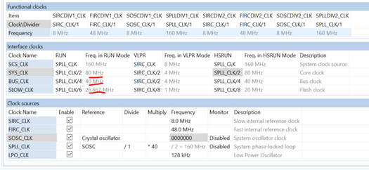
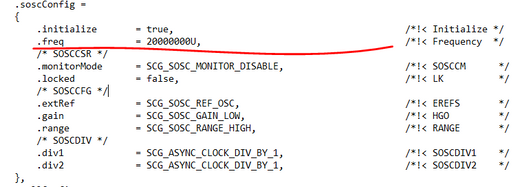
I did the test as you said. like below, it works fine on my side. Hardware based on S32K142EVB,the Crystal oscillator is 8M, however I found that you set crystal oscillator Frequency at 20M, so please check you Crystal oscillator .
S32K142EVB,crystal oscillator 8MHz.
Please check red line highlight,
The attachments was create by me, for reference only.
BR!
Jim,
Hi Jim,
the S32K142 is placed on a PCB designed on my own. The external oscillator has a resonance frequency at 20MHz. But I have an idea what could cause the trouble. The Datasheet says, that the reference clock of the PLL must lie between 8 and 16MHz what would implicate that I have to set the reference clock divider to two (0b001). Could that be the problem?
Best Regards
Tom
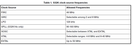
1.Refers to: AN5408
The SOSC can source from either a signal driven into the EXTAL pin or a crystal oscillator connected to the XTAL and EXTAL pins (henceforth referred as simply “XTAL”).EXTAL can support up to 50 MHz, while there are two ranges that are allowed for the XTAL depending on configuration: 4-8 MHz or 8-40 MHz;
So, we can pretty sure that 20MHz XTAL is supported by S32K142.
---------------------------------------------------------------------------------------------------------------------------
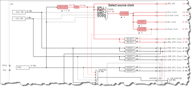
2.Then we discuss about reason that cause the error.
That was your configuration.
Clock configurate Tool show error.
Limits.
| SPLL_VCO_CLK (min) | 180 |
| SPLL_VCO_CLK (max) | 320 |
and about Flash clock.
If you want set Flash clock = 26.667MHz, then .divSlow = SCG_SYSTEM_CLOCK_DIV_BY_3,
-------------------------------------------------------------------------------------------------------------------------------
Try this configuration.
BR!
Jim,
---------------------------------------------------------------------------------------------------------------------------------------
Note:
- If this post answers your question, please click the "Mark Correct" button. Thank you!
- We are following threads for 7 weeks after the last post, later replies are ignored
Please open a new thread and refer to the closed one, if you have a related question at a later point in time.
---------------------------------------------------------------------------------------------------------------------------------------
Hi Jim,
i agree with the flash-clock option. But when I type the following configuration into the clock calculator AN5408SW it says that everything should work fine:
.rccrConfig =              /*!< RCCR - Run Clock Control Register          */
            {
                .src=SCG_SYSTEM_CLOCK_SRC_SYS_PLL,                  /*!< SCS        SPLL  @ 160MHz   */
                .divCore      = SCG_SYSTEM_CLOCK_DIV_BY_2,                     /*!< DIVCORE    Core  @ 80MHz    */
                .divBus       = SCG_SYSTEM_CLOCK_DIV_BY_2,                     /*!< DIVBUS     Bus   @ 40Mhz    */
                .divSlow      = SCG_SYSTEM_CLOCK_DIV_BY_4,                     /*!< DIVSLOW    Flash @ 26.67MHz */
            },
Best regards
Tom
Sorry i read wrong
My colleague suggested to check Hardfault's specific reasons first.
Can you use an oscilloscope to detect the waveform? Is the clock waveform correct?
If the predivider is set larger, such as 4, will it work?
Our laboratory does not have a 20MHz crystal oscillator. Otherwise, I can help you reproduce the problem quickly. I can only guess the possible cause.
Can you send me your clock configuration file, let me double check.
BR!
Jim,
Maybe the following information may also help you:
When I do operations in a while-loop which are not accessing peripheral registers everything works fine.
CLOCK_DRV_Init(*g_clockManConfigsArr);

int x = 0;

while(1)
{
   x++;
}
I will check the waveform of the oscillator and will test some other configurations.
Best regards
Tom
Edit:
Here are the shots from the oscilloscope.


I tried to configure according to the configuration file you sent me. I found that the clock configuration tool reported an error. You can change this place and test it again.
            .hccrConfig =              /*!< HCCR - HSRUN Clock Control Register        */
            {
                .src=SCG_SYSTEM_CLOCK_SRC_SYS_PLL,                  /*!< SCS        */
                .divCore      = SCG_SYSTEM_CLOCK_DIV_BY_2,                     /*!< DIVCORE    */
                .divBus       = SCG_SYSTEM_CLOCK_DIV_BY_2,                     /*!< DIVBUS     */
                .divSlow      = SCG_SYSTEM_CLOCK_DIV_BY_4,                     /*!< DIVSLOW    */
            },
BR!
Jim,
Hi Jim,
finally it is working! But I don't understand why the high speed run settings do affect the microcontroller operation in normal mode. Anyways, it works!
Is it okay, that the sine wave looks so distorted at the XTAL_Pin. Or should I try to operate the SOSC in the high gain mode? What is the advantage of operating the SOSC in the high gain mode? I guess it is more stable but more power consuming as well.
Maybe you can send me oscilloscope shots from the evaluation board as reference?
Best regards
Tom
Finally solved the problem!
Sorry for the late reply, cause the time zone.
As I said above, I only have an 8MHz crystal oscillator. Do you need me to record the waveform and send it to you?
BR!
Jim,


