
- Forums
- Product Forums
- General Purpose MicrocontrollersGeneral Purpose Microcontrollers
- i.MX Forumsi.MX Forums
- QorIQ Processing PlatformsQorIQ Processing Platforms
- Identification and SecurityIdentification and Security
- Power ManagementPower Management
- Wireless ConnectivityWireless Connectivity
- RFID / NFCRFID / NFC
- Advanced AnalogAdvanced Analog
- Neural Processing UnitsNeural Processing Units
- MCX Microcontrollers
- S32G
- S32K
- S32V
- MPC5xxx
- Other NXP Products
- S12 / MagniV Microcontrollers
- Powertrain and Electrification Analog Drivers
- Sensors
- Vybrid Processors
- Digital Signal Controllers
- 8-bit Microcontrollers
- ColdFire/68K Microcontrollers and Processors
- PowerQUICC Processors
- OSBDM and TBDML
- S32M
- S32Z/E
-
- Solution Forums
- Software Forums
- MCUXpresso Software and ToolsMCUXpresso Software and Tools
- CodeWarriorCodeWarrior
- MQX Software SolutionsMQX Software Solutions
- Model-Based Design Toolbox (MBDT)Model-Based Design Toolbox (MBDT)
- FreeMASTER
- eIQ Machine Learning Software
- Embedded Software and Tools Clinic
- S32 SDK
- S32 Design Studio
- GUI Guider
- Zephyr Project
- Voice Technology
- Application Software Packs
- Secure Provisioning SDK (SPSDK)
- Processor Expert Software
- Generative AI & LLMs
-
- Topics
- Mobile Robotics - Drones and RoversMobile Robotics - Drones and Rovers
- NXP Training ContentNXP Training Content
- University ProgramsUniversity Programs
- Rapid IoT
- NXP Designs
- SafeAssure-Community
- OSS Security & Maintenance
- Using Our Community
-
- Cloud Lab Forums
-
- Knowledge Bases
- ARM Microcontrollers
- i.MX Processors
- Identification and Security
- Model-Based Design Toolbox (MBDT)
- QorIQ Processing Platforms
- S32 Automotive Processing Platform
- Wireless Connectivity
- CodeWarrior
- MCUXpresso Suite of Software and Tools
- MQX Software Solutions
- RFID / NFC
- Advanced Analog
- Neural Processing Units
-
- NXP Tech Blogs
- Home
- :
- 产品论坛
- :
- S12 / MagniV微控制器
- :
- Re: XEP100 EEEPROM
XEP100 EEEPROM
XEP100 EEEPROM
I notice in the EEEPROM_Quick_Start.mcp project in the main.c code there is the line..
#define PARTITION_D_FLASH 0x20 /* M48H mask only */
As I am using a different mask (1N35H) could someone tell me how the PARTITION should be modified.
We are using the DEMOAX9S12 evaluation board with the XEP100 device and using the EEEPROM_Quick_Start.mcp project from the downloaded AN3743SW.zip files. I am able to verify the EEEPROM memory functionality by stepping through the code using Codewarrior when connected to the Demo board but when trying to repeat the process on our design of system board with a XEP100 then the FDIV error is displayed whilst executing the step through. I've confirmed the
'#define FCLK_DIV 0x2F // Flash clock divider for 50MHz crystal'
in the CLOCK DIVIDE SECTION is correct and the board/device functions correctly with the rest of the project. This is the second system board with an XEP100 device showing the same problem so I'm confident I've ruled out a device with faulty memory.
Any ideas?
Hi John,
The AN3743 is now quite old application note.
It seems that “M48H mask only” note is rather related to the preproduction masksets (like xM22E, not produced anymore) insted of 1N35H. The 1N35H is newest version produced in TSMC11 fab. It exactly refers to 5M48H maskset from TSMC FAB3 (dual source for avoiding delivery issues).
As correctly mentioned by Daniel, the maximum oscillator frequency for S12XE is specified as 40MHz (Full Swing Pierce oscillator connection, see Table A-4. Operating Conditions in RM).
What oscillator you use on your design of system board?
See Table 24-9. FDIV vs OSCCLK Frequency in RM for obtain correct FCLKDIV register value.
Please look at attached short S12XE EEPROM description and example codes.
I hope it helps you
Best regards
Radek
Hi Radek,
Did you mean to attach something?
Regards
John Thompson
Hi John,
I think that MCU can run with 50MHz external CMOS oscillator, but it is still beyond operating characteristics. So, no guarantee.
Please be aware, that crystal oscillator may be connected in two oscillator connections (Loop Control/Full Swing).
The Full Swing connection should contain external resistor (typ. 1MOhm) in parallel to the crystal. The PE7 (XCLKS) pin should be pulled-down during reset for Full Swing connection and External CMOS oscillator as clock sources.
If the code works on evaluation board and not on your system board, the issue may be also somewhere else. Could you please share your schematic for short review?
If it cannot be shared publicly, please create a service ticket for that.
Best regards
Radek
Hi Radek,
There seems to be a problem with programming the Flash memory on the XEP100 device so please ignore the last message to you.
I have another board with a XEP100 device that I will use. This can be flash programmed via the BDM but still does not execute the EEEPROM Quick Start project successfully.
Regards
John Thompson
Testometric
materials testing machines
Unit 1, Lincoln Business Park
Lincoln Close, Rochdale
Lancashire, England OL11 1NR
Telephone: +44 (0) 1706 654039
Facsimile: +44 (0) 1706 646089
Website: www.testometric.co.uk<blocked::http://www.testometric.co.uk/>;
Reg. No. 1112862 England
P Please consider the environment before printing this email.
Hi John,
Thank you for more information.
Just idea: Do you work with the same project at both boards (50MHz/20MHz)? Or you have different projects with almost the same code?
The default project does not refresh EEEPROM content when we stop MCU. This must be enabled in menu-HC12MultilinkCyclonePro-Debugging Memory Map-global eeprom-refresh memory when halting. Please check whether this option is checked in your project.


Note: The Partition command must not be interrupted (e.g. by any reset), otherwise the D-Flash may be just partially formatted. If you want to check whether D-Flash was correctly formatted, please look at address 0x13F000. There should be two words with sector header. The 0xFFFFFFFF value means, that Partition command was probably interrupted. In that case, you must do mass erase of MCU prior next Partition command execution.
The mass erase is also necessary when you want to change any of partition parameters.
For mass erase go to menu-HC12MultilinkCyclonePro-Unsecure-select appropriate FCLKDIV.
The Full Partition command do not need mass erase, but it could be run only in special mode (=with debugger interface connection).
I hope it helps you.
Best regards
Radek
Hi Radek,
I feel to have exhausted all options here.
I’m comparing behaviour on the DEMOAX9S12 XEP100 board with our project using an XEP100 device using the EEPROM Quick Start project via Debug mode.
The crystal oscillators are the same value 50MHz and XCLKS=0.
The DEMO board works well and programs the DFLASH… see below.
Our system board with the XEP100 device using the EEPROM Quick Start shows a blank DFLASH… see below.
PS. I can flash our system board with another project and it functions as expected but this project does not use DFLASH.
If you have any more ideas what is missing?
Best Regards
John
Hi John,
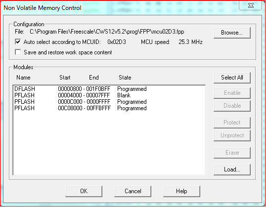
When we load EEPROM Quick Start project into MCU and MCU is not partitioned yet, the DFLASH should be blank as on image002.png.
When we start debugging = stepping through code, the D-Flash become be partitioned and after few steps we will see that DFLASH is Programmed as on image001.png.
It seems, that your system board was not partitioned yet.
So, currently I do not see any issue in described behavior.
BR
Radek
Hi Radeks,
I’ve stepped through the program using the Debug function and the memory is not changing. There are no errors displayed by the Debugger.
I feel there is an issue with the partitioning but I can’t see what the issue is.
Regards
John
Hi John,
- please unsecure your MCU and load AN3743 code into MCU.
- Please write 0x25 into MMCCTL1 register at address 0x0013 for enable EEE IFR visible in memory map.
- After that, please go to Debugging Memory Map - Modify "global eeprom" range 0x100000~0x13FFFF and check "refresh memory when halting".
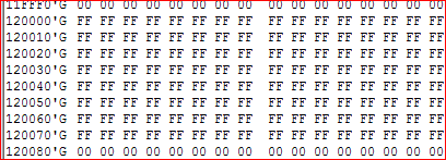
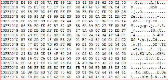
- After that, please go to memory "0x120000'G". There you should see 0x0074 0x0074 0x0001 0x00001 values (DFPART, ERPART and their backups) after partition command execution(/***********(3)PERFORM FULL PARTITION OF EEE RAM***********/)
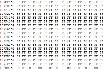
- at address 0x107F00'G you should see 0xFACF 0x0000 value as last sector header. In such case, the D-Flash was correctly formated.
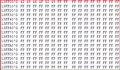
- When you will step over code, you should see EEE values change at address 0x13FF00'G or 0x0F00'L(in such case, please check "refresh memory when halting" also in "eeprom" memory range 0xC00~0xFFF).
See attached memory map for more details about local and global addresses.
I hope it helps you.
Radek
Hi Radek,
Many thanks for continuing to support me to try and resolve this issue.
I’ve confirmed what you have described works OK with the same code on the Demo board.
On our project board the news is disappointing.
I carried out your instructions below with no change to the operation.
I’ve added code to set register MMCCTL1 at 0x0013
At address 0x120000’G there is only 0xFF values after stepping through.
The Debugging Memory Map is setup as you stated.
After partitioning the address 0x107F00’G is 0xFF.
The address starting from 0x13FF00’G is not changing and does not display the same values as with the Demo board from the start.
Stepping through our project an error is displayed as below and the code stops in a ‘while’ loop. See below indicating a problem in the values of FSTAT and FERSTAT registers.
Going back to our project. Before starting the Debug step through the address range from 0x13FF00’G is not correct. See below.
On the Demo board it is as below with ‘BEFORE’ already written to memory starting 0x13FF00’G.
Does this point to some issue at the start.
Regards
John
Hi John,
From your description is clear, that D-Flash was not partitioned (EEE IFR is erased, D-Flash is erased, Buffer RAM content is random).
Please check whether your code has defined “FORCE_PARTITON_FOR_DEBUG”.
You may also check capacitor at VDDF pin. There should be at least 220nF ceramic capacitor (similarly like on VDD, VDDR, and VDDA pins). I already met with a situation where too small capacitor (assembled 470pF instead of 470nF) was not able to cover voltage ripple and it leads to flash command interruption.
I hope it helps you.
Radek
Hi Radek,
I’ve confirmed there are 220nF ceramic capacitors on the VDDF, VDDR, VDD & VDDA pins.
Code referring to partition for Debug mode is defined.
To me, the issue has to be related to differences in the XEP100 device or our board but the EEEPROM Quick Start does not address any external I/O so I suspect the differences will be limited to the:
1) clock source (although same frequency as demo board)
2) mask sets (1N35H & 5M48H look to be the same according to the Errata)
3) decoupling capacitors (200nF as recommended on VDD, VDDR, VDDF, VDDA) on our board.
4) XCLKS is tied to 0v.
... can you think of anything else ?
Regards
John Thompson
Testometric
materials testing machines
Unit 1, Lincoln Business Park
Lincoln Close, Rochdale
Lancashire, England OL11 1NR
Telephone: +44 (0) 1706 654039
Facsimile: +44 (0) 1706 646089
Website: www.testometric.co.uk<blocked::http://www.testometric.co.uk/>;
Reg. No. 1112862 England
P Please consider the environment before printing this email.
Hi Radek,
Looking at the register contents in Debug it is clear to me that the ACCERR flag in the FSTAT register is set when starting the FTM command.
Looking at the FSTAT register contents. The ACCERR flag is set after starting the FTM command above.
This would indicate an illegal access or command has occurred or when initialising the EEE RAM during Reset.
Can you see any reason why this should be different between the Demo board and our board as it is only an internal command.
Hi John,
According to documentation, the ACCERR flag is set for Full Partition D-Flash command when:
1. FCCOBIX[2:0] != 0b010 at command launch
2. command not available in current mode (see Table 24-30)
3. an invalid DFPART or ERPART selection is supplied
If you didn’t change LaunchFlashCommand() command or code line
status = LaunchFlashCommand(2 ,FULL_PARTITION_D_FLASH, 0, DFPART, EEE_RAM, 0, 0, 0, 0, 0);, the first source may be probably excluded.
The Full Partition D-Flash command may be executed only in Unsecured Special Single Chip mode or Unsecured Special Mode. Please check MODE register at address 0x000B whether your MCU running in the correct mode.
Since the selected DFPART or ERPART works on evaluation board with the same type of MCU (S12XEP100), I do not expect that third source may be the root cause. Anyway, please check PARTID registers at addresses 0x001A and 0x001B and compare it with Table 1-6. Assigned Part ID Numbers in RM. There should be 0xCC94 for 5M48H maskset and 0xCC95 for 1N35H maskset as confirmation that you use correct S12XE derivative.
I hope it helps you.
Best regards
Radek
Dear Radek,
The problem is resolved ☺
It was the incorrect MODE selection because of the MODC input due to the pin sharing with BKGD used in Debugger. The EEEPROM Quick Start does not partition the D Flash when in Normal Single Chip mode.
Many thanks for your help and staying with it.
Regards
John
Hi John,
I am glad that the problem is resolved and we found the root cause.
In fact, the debugger typically tied MODC(BKGD) pin low and reset MCU during code loading. This way, the special single chip mode is selected (when MODA=MODB=0).
If you want to partition the D-Flash in normal mode, please use PARTITION_D_FLASH command instead of FULL_PARTITION_D_FLASH. The additional condition is that EEE IFR must be an empty and D-Flash must be erased prior that command (Erase All Blocks must be performed prior any partition change). See example codes attached to my first post here.
I hope it helps you.
Radek
Hi Radek,
The debugger does not successfully manage the MODC/BKGD pin during reset or code loading. The only way to select Special Single chip is to pull down MODC during device reset and then connect the debugger.
Regards
John Thompson
Testometric
materials testing machines
Unit 1, Lincoln Business Park
Lincoln Close, Rochdale
Lancashire, England OL11 1NR
Telephone: +44 (0) 1706 654039
Facsimile: +44 (0) 1706 646089
Website: www.testometric.co.uk<blocked::http://www.testometric.co.uk/>;
Reg. No. 1112862 England
P Please consider the environment before printing this email.
Hi Radek,
Many thanks for keeping with me on this. I think we are on to something here! ☺
Reading the MODE register at address 0x000B on the Demo board has value 0x00 (000) and on our board has value 0x80 which is Normal Single Chip mode (100).
Pins MODA & MODB are tied to 0v.
The MODC pin shares with the BKGD pin and I’m not sure how to change our board so the MODE register reads 000 on Reset.
Regards
John
Hi Radek,
Thank you for your help so far.
My project are not the same as EEPROM Quick Start but I can flash both devices with my project and they function correctly. I have captured the address from 0x13FE00 and I can see that the loaded code is not the same on my project as when I start the EEPROM Quick Start with the DEMOAX9S12 board.
The address 0x13F000 is not as you suggested when loaded into my project.
When I launch the project using Codewarrior using Debug the mass erase is performed.
I’m sorry I can’t find the Debugging Memory Map in the P&E CyclonePro settings.
John
Hi John,
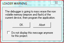
When you click on Debug button, the debugger will erase Flash and EEPROM by sectors – this is not mass erase. Please, do not believe to the information from image003.png warning.
Please use unsecure command if you wish erasing Partitioning.
I would like to apologize. My mistake, that last D-Flash sector starts at address 0x107F00 and not at 0x13F000.
Please make screenshot of your P&E CyclonePro settings.
Mine is:

BR
Radek