
- Forums
- Product Forums
- General Purpose MicrocontrollersGeneral Purpose Microcontrollers
- i.MX Forumsi.MX Forums
- QorIQ Processing PlatformsQorIQ Processing Platforms
- Identification and SecurityIdentification and Security
- Power ManagementPower Management
- Wireless ConnectivityWireless Connectivity
- RFID / NFCRFID / NFC
- Advanced AnalogAdvanced Analog
- Neural Processing UnitsNeural Processing Units
- MCX Microcontrollers
- S32G
- S32K
- S32V
- MPC5xxx
- Other NXP Products
- S12 / MagniV Microcontrollers
- Powertrain and Electrification Analog Drivers
- Sensors
- Vybrid Processors
- Digital Signal Controllers
- 8-bit Microcontrollers
- ColdFire/68K Microcontrollers and Processors
- PowerQUICC Processors
- OSBDM and TBDML
- S32M
- S32Z/E
-
- Solution Forums
- Software Forums
- MCUXpresso Software and ToolsMCUXpresso Software and Tools
- CodeWarriorCodeWarrior
- MQX Software SolutionsMQX Software Solutions
- Model-Based Design Toolbox (MBDT)Model-Based Design Toolbox (MBDT)
- FreeMASTER
- eIQ Machine Learning Software
- Embedded Software and Tools Clinic
- S32 SDK
- S32 Design Studio
- GUI Guider
- Zephyr Project
- Voice Technology
- Application Software Packs
- Secure Provisioning SDK (SPSDK)
- Processor Expert Software
- Generative AI & LLMs
-
- Topics
- Mobile Robotics - Drones and RoversMobile Robotics - Drones and Rovers
- NXP Training ContentNXP Training Content
- University ProgramsUniversity Programs
- Rapid IoT
- NXP Designs
- SafeAssure-Community
- OSS Security & Maintenance
- Using Our Community
-
- Cloud Lab Forums
-
- Knowledge Bases
- ARM Microcontrollers
- i.MX Processors
- Identification and Security
- Model-Based Design Toolbox (MBDT)
- QorIQ Processing Platforms
- S32 Automotive Processing Platform
- Wireless Connectivity
- CodeWarrior
- MCUXpresso Suite of Software and Tools
- MQX Software Solutions
- RFID / NFC
- Advanced Analog
- Neural Processing Units
-
- NXP Tech Blogs
- Home
- :
- モバイル・ロボティクス - ドローンとローバー
- :
- ロボットハードウェア
- :
- Re: RDDRONE-BMS772
RDDRONE-BMS772
- RSS フィードを購読する
- トピックを新着としてマーク
- トピックを既読としてマーク
- このトピックを現在のユーザーにフロートします
- ブックマーク
- 購読
- ミュート
- 印刷用ページ
RDDRONE-BMS772

 iaingalloway
- 新着としてマーク
- ブックマーク
- 購読
- ミュート
- RSS フィードを購読する
- ハイライト
- 印刷
- 不適切なコンテンツを報告
Please ask questions about the RDDRONE-BMS772 board and software here
iaingalloway
- 新着としてマーク
- ブックマーク
- 購読
- ミュート
- RSS フィードを購読する
- ハイライト
- 印刷
- 不適切なコンテンツを報告
When you use JLINK software and a debugger to connect to the BMS, one of the first things JLINK.exe prints out is the voltage on the MCU/debug port.
It's possible that even with external power 22v or whatever, coming in to the BMS board, that the actual power supply feeding the MCU is not turned on.
There is a tiny physical button on the BMS which may wake up the MCU power supply.
https://nxp.gitbook.io/rddrone-bms772/user-guide/getting-to-know-the-hardware/board-organization

- 新着としてマーク
- ブックマーク
- 購読
- ミュート
- RSS フィードを購読する
- ハイライト
- 印刷
- 不適切なコンテンツを報告
Hi, thank you for your answer.
I tried pushing the SW1 button. I tried with the reset jumper and without it.
I tried generating a reset pulse with a signal generator following the electrical specifications in the s32k1xx datasheet. https://www.nxp.com/docs/en/data-sheet/S32K-DS.pdf
I checked all the voltages.
If I connect the FTDI cable some garbage slash noise appears in the Tera Term console when I turn on and off the switch power supply.
- 新着としてマーク
- ブックマーク
- 購読
- ミュート
- RSS フィードを購読する
- ハイライト
- 印刷
- 不適切なコンテンツを報告
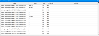
Hello, I was experimenting with the BMS772 this evening and was trying to display cell voltages. I have a 3s setup and for some reason one cell is consistently reading higher than the others. I confirmed via a multimeter that the cells are all roughly the same value. I tried this with two different battery packs as well. See my attached screenshot for more information. Notice, the BMS is consistently reading ~0.7 greater than the others. I am using Model-Based Development with a J-Link Debugger in FreeMaster. Any advice would be appreciated!
cisvmierlo
- 新着としてマーク
- ブックマーク
- 購読
- ミュート
- RSS フィードを購読する
- ハイライト
- 印刷
- 不適切なコンテンツを報告
Hi @dmorvay,
I do not have experience with the Model-Based Development toolbox yet, so in this regard I can not check it.
For the HW:
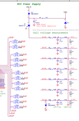
Could you confirm that the soldered jumpers are SJ6, SJ10, SJ11 and SJ12 for 3S?
And the cell voltage filters are correctly in place:
Kind regards,
Cis van Mierlo
- 新着としてマーク
- ブックマーク
- 購読
- ミュート
- RSS フィードを購読する
- ハイライト
- 印刷
- 不適切なコンテンツを報告
@cisvmierlo That seemed to do the trick! It appears that I failed to read that portion of the documentation about soldering those jumpers.
Another question regarding the OLED screen, I tried building and flashing the LED example onto the board, but the screen would not turn on. Is there anything special I need to do there? I was reading 3.3V on J23 between VCC and GND, but when I plugged the screen in, it would not turn on. Any suggestions? I didn't get a chance to check the D34 and D35 diodes today, but do those need to be moved if I am reading 3.3V?
cisvmierlo
- 新着としてマーク
- ブックマーク
- 購読
- ミュート
- RSS フィードを購読する
- ハイライト
- 印刷
- 不適切なコンテンツを報告
Hi @dmorvay,
Great that soldering the correct jumpers solves the cell voltage issue!
For the OLED display, as I said I'm not familiar with the Model Based Design Toolbox examples.
Maybe they mean the RGB-LED which is on the board with the LED example?
The display delivered with the kit should support 3.3V.
But if you are interested in an BMS example project written in C with the NuttX RTOS (this includes the display to showcase battery values), see the example here: https://github.com/NXPHoverGames/RDDRONE-BMS772
PS: This is a graphical display, not a textual display. So each character needs to be drawn according to a specific font that is used.
Kind regards,
Cis van Mierlo
- 新着としてマーク
- ブックマーク
- 購読
- ミュート
- RSS フィードを購読する
- ハイライト
- 印刷
- 不適切なコンテンツを報告
Hi @cisvmierlo, I appreciate the information! I will try again on the display. For reference, what is the I2C transmission voltage on the BMS772? Is it 5V or 3.3V I2C? I don't want to hook up a 5V I2C (say Arduino) and then damage the board if it is 3.3V.
cisvmierlo
- 新着としてマーク
- ブックマーク
- 購読
- ミュート
- RSS フィードを購読する
- ハイライト
- 印刷
- 不適切なコンテンツを報告
Hi @dmorvay ,
The I2C voltage level is 3.3V.
This is the MCU voltage domain as well.
But there is 5V on the board which can be used to supply a display with 5V.
The schematic of the RDDRONE-BMS772 can be downloaded from the NXP webpage (click on design files or scroll down to the design resources):
https://www.nxp.com/design/designs/smart-battery-management-for-mobile-robotics:RDDRONE-BMS772
Kind regards,
Cis van Mierlo
- 新着としてマーク
- ブックマーク
- 購読
- ミュート
- RSS フィードを購読する
- ハイライト
- 印刷
- 不適切なコンテンツを報告
Hi @cisvmierlo
Another question regarding I2C communication: when configuring the BMS772 as a slave, should the pins for SDA/SCL be PTB6 and PTB7 respectively or PTA2 and PTA3 respectively? Looking at the schematics, it seems like it is actually neither of these two options, but instead PTA0 and PTA1. Hence, I am slightly confused on how to setup the board as a slave for I2C communication.
cisvmierlo
- 新着としてマーク
- ブックマーク
- 購読
- ミュート
- RSS フィードを購読する
- ハイライト
- 印刷
- 不適切なコンテンツを報告
Hi @dmorvay ,
The connector J18 can be used for SMBUS / I2CS.
The SMBUS_SCL and SMBUS_SDA lines are connected to this connector.
These lines are connector to PTA0 and PTA1, which support the LPI2C0_SCLS and /LPI2C0_SDAS peripheral.
Kind regards,
Cis van Mierlo
- 新着としてマーク
- ブックマーク
- 購読
- ミュート
- RSS フィードを購読する
- ハイライト
- 印刷
- 不適切なコンテンツを報告
Hi @cisvmierlo
Two more questions based on your answer...
1. Can PTA2 and PTA3 (connector J23) be configured as an I2C slave? On the software side, it seems to be possible, but want to make sure everything checks out in both hardware and software.
2. How do you configure LPI2C0_SCLS and LPI2C0_SDAS? Do you have any references on how to configure this in C code and/or through Model Based Development? I am currently using Model Based Development, but I do not see any peripherals with LPI2C0_SCLS and LPI2C0_SDAS. Additionally, the I2C configuration block only has the options for PTA2/PTA3 or PTB6/PTB7. I am not exactly sure how to activate this output.
 SorinIBancila
- 新着としてマーク
- ブックマーク
- 購読
- ミュート
- RSS フィードを購読する
- ハイライト
- 印刷
- 不適切なコンテンツを報告
Hello @dmorvay,
Regarding the second question, the MBD Toolbox for S32K14x is built on top of the SDK for S32k14x. Unfortunately, it seems that the 4-wire mode is not supported for LPI2C by the SDK, therefore MBD toolbox doesn't support it either.
Best regards,
Bancila Sorin
cisvmierlo
- 新着としてマーク
- ブックマーク
- 購読
- ミュート
- RSS フィードを購読する
- ハイライト
- 印刷
- 不適切なコンテンツを報告
Hi @dmorvay,
I'm not familiar with the MBDT example and what is supported in that toolbox.
For a C / C++ example I would advise you to take a look into the NuttX RTOS SW example.
In this example you can get the BMS data via I2C by reading the correct I2C addresses as stated in Table 6. SMBus variable list (Of chapter 7.5 How to use SMBus).
This example is located here: https://github.com/NXPHoverGames/RDDRONE-BMS772
It will need the NuttX RTOS sources as well: https://github.com/apache/nuttx
See the RDDRONE-BMS772 board in the NuttX repository:
https://github.com/apache/nuttx/tree/master/boards/arm/s32k1xx/rddrone-bms772
And the S32K1xx architecture specific logic:
https://github.com/apache/nuttx/tree/master/arch/arm/src/s32k1xx
I hope this helps you!
Kind regards,
Cis van Mierlo
- 新着としてマーク
- ブックマーク
- 購読
- ミュート
- RSS フィードを購読する
- ハイライト
- 印刷
- 不適切なコンテンツを報告
Hi @cisvmierlo ,
Thank you for this information. I am still unsure about the answer to my first question - Can PTA2/PTA3 (J23) be configured as an I2C slave? Are there any limitations on this I/O that it always has to be configured as a master?
cisvmierlo
- 新着としてマーク
- ブックマーク
- 購読
- ミュート
- RSS フィードを購読する
- ハイライト
- 印刷
- 不適切なコンテンツを報告
Hi @dmorvay,
I think it would be possible to multiplex the I2CS to the PTA2/PTA3 pins.
I would check the S32K-RM chapter 52: Low Power Inter-Integrated Circuit (LPI2C) for this.
But then you need to make the correct changes in the code, I do not know if the SDK supports this.
Kind regards,
Cis van Mierlo
- 新着としてマーク
- ブックマーク
- 購読
- ミュート
- RSS フィードを購読する
- ハイライト
- 印刷
- 不適切なコンテンツを報告
Hi,
Does BMS772 board support Pixhawk Cube Orange Autopilot?
I have successfully communicated with other UAVCAN devices such as Zubax ESC, Packet digital MPPT. links given below. But it didn't work with BMS772.
https://packetdigital.com/power-products/maximum-power-point-tracker/
https://files.zubax.com/products/com.zubax.telega/Zubax_Myxa_Datasheet.pdf
Also, Does BMS772 board support classical CAN (CAN 2.0) protocol? If yes, I would like to test it with Microchip's CAN bus analyzer.
Please clarify.
Thanks in advance..
- 新着としてマーク
- ブックマーク
- 購読
- ミュート
- RSS フィードを購読する
- ハイライト
- 印刷
- 不適切なコンテンツを報告
Request for Register Map for NXP RDDrone-BMS772
Hi all,
I recently purchased the NXP RDDrone-BMS772 battery management system for my project, and I am having trouble communicating with the device via I2C. I have been trying to read the registers of the device, but without a register map, it's difficult to know which registers to access.
I was wondering if someone could please provide me with a register map for the RDDrone-BMS772, or point me in the direction of where I could find one. I believe that having a register map would greatly help me to communicate with the device and extract the information that I need.
Thank you for your help in advance.
Best regards,
- 新着としてマーク
- ブックマーク
- 購読
- ミュート
- RSS フィードを購読する
- ハイライト
- 印刷
- 不適切なコンテンツを報告
The Smart Battery System Specification ended up being helpful.
The spec sheet can be found here:
iaingalloway
- 新着としてマーク
- ブックマーク
- 購読
- ミュート
- RSS フィードを購読する
- ハイライト
- 印刷
- 不適切なコンテンツを報告
The best reference for what is implemented is by referring to the actual code. Which is published and open source.
- 新着としてマーク
- ブックマーク
- 購読
- ミュート
- RSS フィードを購読する
- ハイライト
- 印刷
- 不適切なコンテンツを報告
Does anyone know where can I purchase other suitable debugger for NXP RDDRONE-BMS apart from J-Link or PEMicro ?? Thank you.
iaingalloway
- 新着としてマーク
- ブックマーク
- 購読
- ミュート
- RSS フィードを購読する
- ハイライト
- 印刷
- 不適切なコンテンツを報告
This isn't helpful according to your question, but the code was developed using a segger jlink family device. If you are a student and this is non-commercial use, you can use one of the lower cost jlink-edu from suppliers like Adafruit.
