
- Forums
- Product Forums
- General Purpose MicrocontrollersGeneral Purpose Microcontrollers
- i.MX Forumsi.MX Forums
- QorIQ Processing PlatformsQorIQ Processing Platforms
- Identification and SecurityIdentification and Security
- Power ManagementPower Management
- Wireless ConnectivityWireless Connectivity
- RFID / NFCRFID / NFC
- Advanced AnalogAdvanced Analog
- Neural Processing UnitsNeural Processing Units
- MCX Microcontrollers
- S32G
- S32K
- S32V
- MPC5xxx
- Other NXP Products
- S12 / MagniV Microcontrollers
- Powertrain and Electrification Analog Drivers
- Sensors
- Vybrid Processors
- Digital Signal Controllers
- 8-bit Microcontrollers
- ColdFire/68K Microcontrollers and Processors
- PowerQUICC Processors
- OSBDM and TBDML
- S32M
- S32Z/E
-
- Solution Forums
- Software Forums
- MCUXpresso Software and ToolsMCUXpresso Software and Tools
- CodeWarriorCodeWarrior
- MQX Software SolutionsMQX Software Solutions
- Model-Based Design Toolbox (MBDT)Model-Based Design Toolbox (MBDT)
- FreeMASTER
- eIQ Machine Learning Software
- Embedded Software and Tools Clinic
- S32 SDK
- S32 Design Studio
- GUI Guider
- Zephyr Project
- Voice Technology
- Application Software Packs
- Secure Provisioning SDK (SPSDK)
- Processor Expert Software
- Generative AI & LLMs
-
- Topics
- Mobile Robotics - Drones and RoversMobile Robotics - Drones and Rovers
- NXP Training ContentNXP Training Content
- University ProgramsUniversity Programs
- Rapid IoT
- NXP Designs
- SafeAssure-Community
- OSS Security & Maintenance
- Using Our Community
-
- Cloud Lab Forums
-
- Knowledge Bases
- ARM Microcontrollers
- i.MX Processors
- Identification and Security
- Model-Based Design Toolbox (MBDT)
- QorIQ Processing Platforms
- S32 Automotive Processing Platform
- Wireless Connectivity
- CodeWarrior
- MCUXpresso Suite of Software and Tools
- MQX Software Solutions
- RFID / NFC
- Advanced Analog
- Neural Processing Units
-
- NXP Tech Blogs
- Home
- :
- Mobile Robotics - Drones and Rovers
- :
- Robotic Hardware
- :
- Re: RDDRONE-BMS772
RDDRONE-BMS772
- Subscribe to RSS Feed
- Mark Topic as New
- Mark Topic as Read
- Float this Topic for Current User
- Bookmark
- Subscribe
- Mute
- Printer Friendly Page
RDDRONE-BMS772

 iaingalloway
- Mark as New
- Bookmark
- Subscribe
- Mute
- Subscribe to RSS Feed
- Permalink
- Report Inappropriate Content
Please ask questions about the RDDRONE-BMS772 board and software here

- Mark as New
- Bookmark
- Subscribe
- Mute
- Subscribe to RSS Feed
- Permalink
- Report Inappropriate Content
A1007 Secure Authenticator
Hi community, I have just started developing with the BMS772. However, I can not find any information on the A1007 IC.
I can not even find this IC on the NXP site of any of our usual suppliers, Digi-Key etc.
Is this IC obsolete?
If so, are there any suggested alternative.
Thanks
cisvmierlo
- Mark as New
- Bookmark
- Subscribe
- Mute
- Subscribe to RSS Feed
- Permalink
- Report Inappropriate Content
In the following NXP community page it is stated that the documentation and software is available on DocStore. It also explains how to get access to DocStore.
So I believe the A1007 is available under NDA only.
Link to the NXP community page: https://community.nxp.com/t5/Other-NXP-Products/OM67201UL-driver-A1007/m-p/1447573
If you are looking to build something yourself, I would recommend to look at the common available NXP IoT Security and Authentication Portfolio: https://www.nxp.com/iotsecurity
For example, the SE050 or SE051 is a greatly supported device, with lots of use cases already implemented.
If you would like to develop on a board with an SE050 and a similar MCU (S32K146 instead of S32K144). The UCANS32K146 might be an interesting product.
Link to the SE050: https://www.nxp.com/products/security-and-authentication/authentication/edgelock-se050-plug-trust-se...
Link to the UCANS32K146: https://www.nxp.com/design/development-boards/automotive-development-platforms/s32k-mcu-platforms/s3...
I hope this answers your questions, kind regards,
Cis van Mierlo
- Mark as New
- Bookmark
- Subscribe
- Mute
- Subscribe to RSS Feed
- Permalink
- Report Inappropriate Content
Thank you @cisvmierlo.
Very useful information.
- Mark as New
- Bookmark
- Subscribe
- Mute
- Subscribe to RSS Feed
- Permalink
- Report Inappropriate Content
Hi,
I bought a new RDDRONE-BMS772 board and want to use it for 4S LiPo battery pack. I have soldered Cell terminal connector and Solder jumper pins (SJ) for 4S. After connecting to 4S pack, When I measured the output voltage it is 0V. I don't know why.
Shall I do any configuration change(for 4S) in the software also? If so, how? Please reply.
Thanks in advance.
iaingalloway
- Mark as New
- Bookmark
- Subscribe
- Mute
- Subscribe to RSS Feed
- Permalink
- Report Inappropriate Content
Note that if you want to just use the serial console to see what is going on internally (and not reprogram and debug the board) Then you can buy any FTDI type USB-UART cable (or use a PC with a UART) to connect a serial console to the BMS772. Normally this is broken out on the DCD-LZ board so it can be plugged in easily.
Here is the type of cable you would buy at Amazon or Digikey or whereever:
https://www.digikey.com/en/products/detail/ftdi-future-technology-devices-international-ltd/TTL-234X...
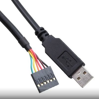
You would then use a JST-GH connector to attach to the RX TX and GND pins of the DCD-LZ interface on the BMS - do NOT connect the power from the FTDI cable to the DCD-LZ:
The pinout is shown here:
https://nxp.gitbook.io/hovergames/rddrone-fmuk66/connectors/debug-interface-dcd-lz/dcd-lz-breakout-b...
- Mark as New
- Bookmark
- Subscribe
- Mute
- Subscribe to RSS Feed
- Permalink
- Report Inappropriate Content
Hi iaingalloway,
Thanks for your reply.
I want to change the BMS configuration from default 3S to 4S and also change battery chemistry through serial console. Is FTDI type USB-UART cable connected to JST GH 7 pin connector (only Tx, Rx, GND pins) is sufficient for this?
I am also trying to get J link EDU mini debugger to update firmware, but it's lead time is 40 weeks. So, Just trying to update configuration parameters as of now.
Thanks..
cisvmierlo
- Mark as New
- Bookmark
- Subscribe
- Mute
- Subscribe to RSS Feed
- Permalink
- Report Inappropriate Content
Hi @Prince1,
Yes you only need to connect GND, TX and RX as seen in this screenshot:
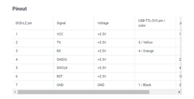
Keep in mind that a USB-TTL-3V3 is used, this ensures 3.3V logic level on the RX and TX pins.
Kind regards,
Cis van Mierlo
- Mark as New
- Bookmark
- Subscribe
- Mute
- Subscribe to RSS Feed
- Permalink
- Report Inappropriate Content
Hi,
I have PL2303HX USB To TTL(Serial) Converter which provides 3.3V on Tx, Rx and GND.
https://robu.in/product/pl2303-pl2303hx-usb-ttl-module-5-pin/
With this Can I attempt software reconfiguration?
PL2303HX will be inserted in USB port and its TX, RX, GND pins are connected to respective pins in J19 port. Do I need to connect battery also to BMS (to J4) to power it's circuit? If so, 4S or 3S battery?
As in my BMS, 4S cell terminal connector is soldered in JP1 and SJ3, SJ7, SJ11 and SJ12 are connected, but its factory default configuration in software is 3S. So, I am confused.
Thanks..
 GeraldP
- Mark as New
- Bookmark
- Subscribe
- Mute
- Subscribe to RSS Feed
- Permalink
- Report Inappropriate Content
Hi @Prince1, the SW will just report an error and power out will be not enabled if you have a battery connected that has different cell numbering than configured.
Battery needs to be connected to be able to configure the BMS.
So the way to setup the BMS is:
- connect your UART adapter and open terminal SW with 115k2 8n1 serial port setting.
- Connect balancer and main power connector of battery to the BMS
- see bootup sequence First start-up - RDDRONE-BMS772 (gitbook.io)
- configure the bms via command line Command Line Interface (CLI) - RDDRONE-BMS772 (gitbook.io)
bms set <parameter name> <value> Parameters of the BMS - RDDRONE-BMS772 (gitbook.io)
- finish with bms save
if you type reboot the BMS will reboot with correct settings and will activate output in case no errors.
https://www.youtube.com/@gdk7xe974
- Mark as New
- Bookmark
- Subscribe
- Mute
- Subscribe to RSS Feed
- Permalink
- Report Inappropriate Content
Hi GeraldP,
I have done the following on a new BMS,
SJ6, 10, 11, 12 are shorted for 3S configuration.
3S LiPo battery is connected to J4 and their cell balancing wires connected to JP1
pins 5, 4, 1 of FTDI USB UART are connected to pins 2, 3, 7 of J19 respectively and then connected to PC
115k2 8n1, Parity: None, Flow: None configured in COM port properties and Tera Term
The result is as follows,
BMS LED is blinking in red colour and then goes OFF after around 1min. I think it goes to SLEEP.
BMS output voltage at J5 is zero (load is not connected)
Tera Term window displays blank screen and doesn't take keyboard input
Display connected to J23 doesn't turn ON
Kindly help me in sorting out above issues.
I tried the same things on another BMS, in which LED doesn't turn ON and SBC chip is getting over heated.
Thanks..
cisvmierlo
- Mark as New
- Bookmark
- Subscribe
- Mute
- Subscribe to RSS Feed
- Permalink
- Report Inappropriate Content
Hi @Prince1,
"BMS LED is blinking in red colour and then goes OFF after around 1min. I think it goes to SLEEP."
This indicates that there is a cell under-voltage detected (based on default battery technology: LiPo).
When this happens, the BMS goes to DEEP_SLEEP after t-fault-timeout (60s default) in order to preserve the battery with its lowest power mode.
In that DEEP_SLEEP state the MCU (and SBC) is turned off, so no communication is possible after that 1 min. The button is press (or a re-power) is the only thing to wake the BMS from the DEEP_SLEEP state.
So it could be that there is no communication because the BMS entered the DEEP_SLEEP.
Or there would be something with the connection.
For the display to turn on during initialization, could you maybe check that D34 is placed instead of D35?
For the other BMS setup, the SBC overheating and LED not turning on, indicates that there might be a short on the 3.3V domain (shorted to gnd).
Could you maybe show both of your boards (top and bottom side)?
Kind regards,
Cis van Mierlo
- Mark as New
- Bookmark
- Subscribe
- Mute
- Subscribe to RSS Feed
- Permalink
- Report Inappropriate Content
Hi Cis van Mierlo,
BMS default V-cell-UV may be 3V, but my all battery cell voltages are beyond 3.8V and 3S pack voltage is 11.5V. I think under voltage is not the reason for BMS going into Deep_Sleep.
Please mention what could be other reasons for BMS LED blinking in red for 1min and then going into Deep_Sleep.
D34 is placed, D35 not placed. Still Display doesn't turn on. Display pin numbers are connected as suggested.
I will share the images of other BMS board with over heating issue.
Thanks..
cisvmierlo
- Mark as New
- Bookmark
- Subscribe
- Mute
- Subscribe to RSS Feed
- Permalink
- Report Inappropriate Content
Hi @Prince1,
Only with a cell under voltage detection it will go to deep-sleep after 1 min.
Maybe there is something with the cell connections.
could you perhaps share images of this board as well (top and bottom)?
Kind regards,
Cis van Mierlo
- Mark as New
- Bookmark
- Subscribe
- Mute
- Subscribe to RSS Feed
- Permalink
- Report Inappropriate Content
Hi @CisvanMierlo,
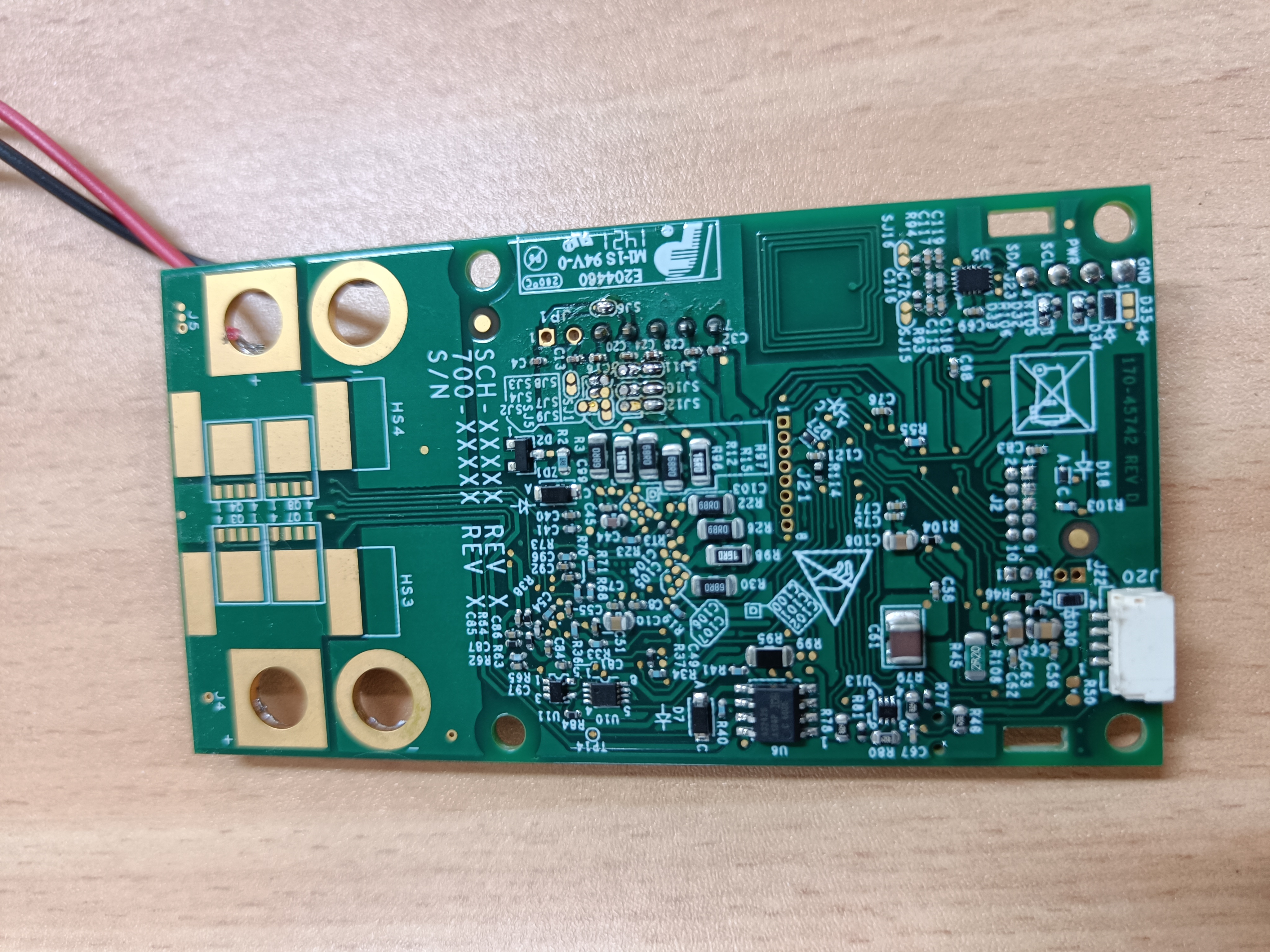
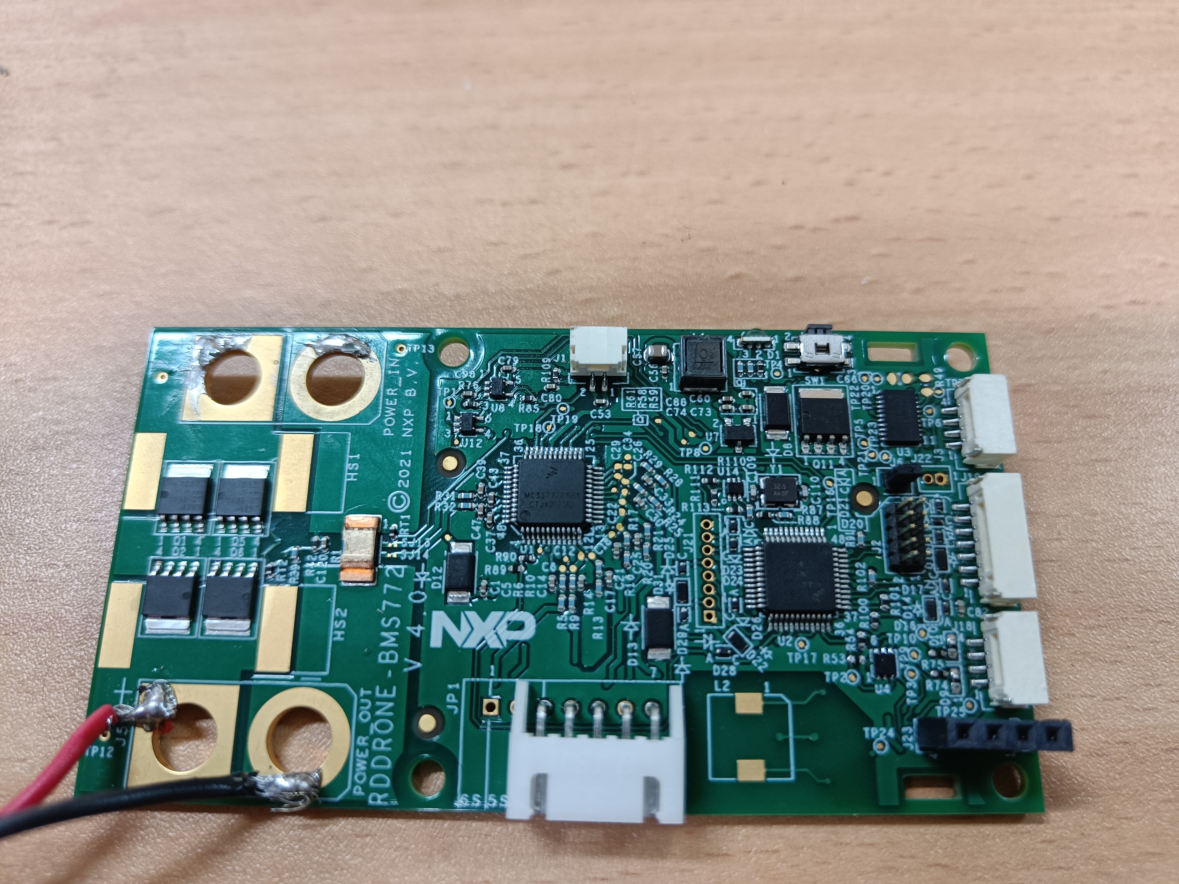
I have attached images of two BMSes,
1st one: LED blinks in red for 1 min before going to Deep_Sleep.
2nd one: has over heat issue and LED doesn't turn ON.
Though I have used 5 pin cell terminal connector, I have not connected 4S pin (5th pin open) / wire. So, 5 pin connector is used for 3S battery. Voltages are correct at JP1 connector.
Today I charged battery to 11.7V and tested still same result.
Thanks..


 cisvmierlo
- Mark as New
- Bookmark
- Subscribe
- Mute
- Subscribe to RSS Feed
- Permalink
- Report Inappropriate Content
Hi @Prince1,
I think I found the issue with the communication on BMS1.
The black wire is connected to J19 pin 1, which is 3.3V and not connected to ground.
For ground, you need to connect the black wire to J19 pin 7 (other side of the connector).
Light blue is now connected to J19 pin 5 (SWD_CLK) and yellow is now connected to J19 pin 6 (RST_N).
I think you need to swap the connections on the connector J19.
I will come back on the other PCB later.
Kind regards,
Cis van Mierlo
- Mark as New
- Bookmark
- Subscribe
- Mute
- Subscribe to RSS Feed
- Permalink
- Report Inappropriate Content
Hi @cisvmierlo ,
Thanks a lot.
You solved my problem.
After rectifying J19 connections, CLI and Display worked.
Yes, CLI shows "Cell undervoltage detected!" and display shows 11.26V although fluke instrument measures 11.7V.
1. It looks if cell voltages < 3.8V, it goes to Deep_Sleep. Will it happen even if load is connected on J5? I mean, if load is connected disconnecting the battery at 3.8V is too early when cell cutoff voltage is 3V.
2. Is it possible to reduce the voltage measurement error in BMS?
Kindly answer the above questions.
Thanks..
cisvmierlo
- Mark as New
- Bookmark
- Subscribe
- Mute
- Subscribe to RSS Feed
- Permalink
- Report Inappropriate Content
Hi @Prince1,
Great that the communication issue has been resolved!
For the other questions:
"Yes, CLI shows "Cell under voltage detected!" and display shows 11.26V although fluke instrument measures 11.7V."
The display shows v-out. Which is measured via a resistor divider on the output with 1% tolerance. Meaning that you could have a 0.946V difference on 26V, just because of the resistor tolerances.
So it could be that this is a little off with the actual value. In the current SW example there is no option to fine tune this measurement.
What you could do is: look at v-batt or add all the cell voltages together (which is the most precise). Vtot = v-cell1 + v-cell2 + ..
"1. It looks if cell voltages < 3.8V, it goes to Deep_Sleep. Will it happen even if load is connected on J5? I mean, if load is connected disconnecting the battery at 3.8V is too early when cell cutoff voltage is 3V."
So the default cell under voltage (for a LiPo battery) is set at 3V. You could check this setting via the UART interface via:
bms get v-cell-uv
You could set the cell under voltage you think is suitable with: "bms set v-cell-uv x.xV"
After setting parameters, do not forget to save it to flash with "bms save".
For more information on which parameters there are, please have a look at chapter 8.2 of BMS772_releaseNotes_5.0.pdf.
But I would check the cell voltages via the UART connection, so you can see which cell has a problem.
You can use: "bms get all" (gets all parameters), "bms show all 1" (updates the battery values), "bms show top 1" (updates the battery values without scrolling).
"2. Is it possible to reduce the voltage measurement error in BMS?"
As stated in the beginning, there is no parameter for correcting the v-out voltage.
But feel free to adjust the SW yourself so for example v-batt is displayed on the display instead of v-out.
Kind regards,
Cis van Mierlo
- Mark as New
- Bookmark
- Subscribe
- Mute
- Subscribe to RSS Feed
- Permalink
- Report Inappropriate Content
Hi @cisvmierlo,
Thanks for your help. I could solve Under voltage fault problem. Now I want to see DroneCAN / UAVCAN messages / parameters sent by BMS in some software tool.
Do you have some software GUI tool to see CAN messages from BMS?
I tried to see messages with DroneCAN GUI tool with BMS772 connected to Orange Cube Autopilot. But I am not successful. Mission planner software didn't recognize BMS in SLCAN mode.
Where as Cube orange detects other UAVCAN devices such as Zubax ESC, Packet digital MPPT.
Also, Should I change DroneCAN static node ID to other than 255 for it to work?
NXP's UCAN based nodes are not available for purchase in India.
Also, please clarify whether Over current, output short circuit protection is available on BMS?
Please clarify the above. Thanks again for your great support.
...
- Mark as New
- Bookmark
- Subscribe
- Mute
- Subscribe to RSS Feed
- Permalink
- Report Inappropriate Content
Hi GeraldP,
Thanks for your help. I will try the way you suggested.
cisvmierlo
- Mark as New
- Bookmark
- Subscribe
- Mute
- Subscribe to RSS Feed
- Permalink
- Report Inappropriate Content
Hi @Prince1,
Indeed you would need to configure the software accordingly.
This can be done as followed:
1. Hook up the DCD-LZ adapter to the BMS772 board using the 7-pins JST-GH cable.
2. Hook up the DCD-LZ adapter to a laptop or PC with a FTDI USBUART-3V3 cable.
3. Connect to the BMS772 over a serial interface, like PuTTY or TeraTerm (115200 Baud).
4. Type "bms help" to get the help for the Command Line Interface (CLI).
5. Type "bms get all" to get all the parameters and the values associated with those parameters.
6. Change the variable you would like to change, in this case n-cells to 4, type: "bms set n-cells 4"
7. To make sure the parameters are saved to flash, type: "bms save"
8. After the new parameter settings, you could either press the button or type: "bms reset" to reset the fault.
The CLI is very useful as it will indicate what caused the error.
Here are some useful links to get started:
A link about setting up the CLI: https://nxp.gitbook.io/rddrone-bms772/user-guide/getting-started-with-the-rddrone-bms772/using-the-c...
A link about using the CLI: https://nxp.gitbook.io/rddrone-bms772/software-guide-nuttx/command-line-interface-cli
A link with a list of parameters: https://nxp.gitbook.io/rddrone-bms772/software-guide-nuttx/untitled-1
Chapter 7 of the release notes (rev. 5) is useful as well as this contains a picture of the DCD-LZ adapter with the 7-pins JST GH cable and the USB-TTL-3V3 cable connected to it.
Chapter 8 includes the parameters of the BMS772.
I would recommend the update the software to the latest binary.
The latest binary can be found at: https://github.com/NXPHoverGames/RDDRONE-BMS772/tree/main/Binary
Instructions can be found in chapter 7 of the release notes, on the code repository or on the gitbook: https://nxp.gitbook.io/rddrone-bms772/user-guide/getting-started-with-the-rddrone-bms772/flashing-fi...
Keep in mind that after programming, you need to re-configure the parameters again as these get overwritten.
I hope this helps, kind regards,
Cis van Mierlo
- Mark as New
- Bookmark
- Subscribe
- Mute
- Subscribe to RSS Feed
- Permalink
- Report Inappropriate Content
Hi,
Thanks for your quick reply. Unfortunately, I couldn't find distributor to purchase DCD-LZ adapter in India. I don't have a hover games kit as well.
Can you suggest any alternative adapter which is widely available?
Thanks.
