
- Forums
- Product Forums
- General Purpose MicrocontrollersGeneral Purpose Microcontrollers
- i.MX Forumsi.MX Forums
- QorIQ Processing PlatformsQorIQ Processing Platforms
- Identification and SecurityIdentification and Security
- Power ManagementPower Management
- Wireless ConnectivityWireless Connectivity
- RFID / NFCRFID / NFC
- Advanced AnalogAdvanced Analog
- Neural Processing UnitsNeural Processing Units
- MCX Microcontrollers
- S32G
- S32K
- S32V
- MPC5xxx
- Other NXP Products
- S12 / MagniV Microcontrollers
- Powertrain and Electrification Analog Drivers
- Sensors
- Vybrid Processors
- Digital Signal Controllers
- 8-bit Microcontrollers
- ColdFire/68K Microcontrollers and Processors
- PowerQUICC Processors
- OSBDM and TBDML
- S32M
- S32Z/E
-
- Solution Forums
- Software Forums
- MCUXpresso Software and ToolsMCUXpresso Software and Tools
- CodeWarriorCodeWarrior
- MQX Software SolutionsMQX Software Solutions
- Model-Based Design Toolbox (MBDT)Model-Based Design Toolbox (MBDT)
- FreeMASTER
- eIQ Machine Learning Software
- Embedded Software and Tools Clinic
- S32 SDK
- S32 Design Studio
- GUI Guider
- Zephyr Project
- Voice Technology
- Application Software Packs
- Secure Provisioning SDK (SPSDK)
- Processor Expert Software
- Generative AI & LLMs
-
- Topics
- Mobile Robotics - Drones and RoversMobile Robotics - Drones and Rovers
- NXP Training ContentNXP Training Content
- University ProgramsUniversity Programs
- Rapid IoT
- NXP Designs
- SafeAssure-Community
- OSS Security & Maintenance
- Using Our Community
-
- Cloud Lab Forums
-
- Knowledge Bases
- ARM Microcontrollers
- i.MX Processors
- Identification and Security
- Model-Based Design Toolbox (MBDT)
- QorIQ Processing Platforms
- S32 Automotive Processing Platform
- Wireless Connectivity
- CodeWarrior
- MCUXpresso Suite of Software and Tools
- MQX Software Solutions
- RFID / NFC
- Advanced Analog
- Neural Processing Units
-
- NXP Tech Blogs
- Home
- :
- Software Forums
- :
- Processor Expert Software
- :
- [LS1028A]:QSGMII link is not coming in Linux
[LS1028A]:QSGMII link is not coming in Linux
- Subscribe to RSS Feed
- Mark Topic as New
- Mark Topic as Read
- Float this Topic for Current User
- Bookmark
- Subscribe
- Mute
- Printer Friendly Page
[LS1028A]:QSGMII link is not coming in Linux
- Mark as New
- Bookmark
- Subscribe
- Mute
- Subscribe to RSS Feed
- Permalink
- Report Inappropriate Content
Dear NXP Support Team,
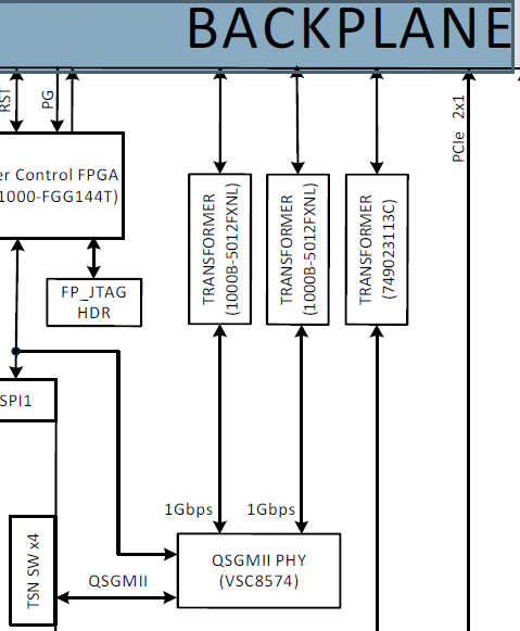
We have two lLS1028A based custom board in which QSGMII PHY (VSC8574) switch is connected through Ethernet controller (ENETC) in processor. Port1 of PHY switch is connected to another board at port0.
We are doing below configuration according to VSC8574 datasheet(section: 3.21 Configuration) in U-Boot prompt and getting QSGMII PHY LINK is up ,Autonegotiation complete bit is also 1 and corresponding LED is glowing in both the board:
#Config for board 1
mii device emdio-3
mii write 0x11 0x1f 0x10
mii write 0x11 0x13 0x0
mii write 0x11 0x12 0x80e0
mii write 0x11 0x1f 0x0
mii write 0x11 0x17 0x1800
mii write 0x11 0x13 0x4001
mii write 0x11 0x00 0x9340
mii read 0x11 0x00 0x2
gpio clear 75
mii read 0x11 0x01 0x2
--------------------
#config for board2
mii device emdio-3
mii write 0x10 0x1f 0x10
mii write 0x10 0x13 0x0
mii write 0x10 0x12 0x80e0
mii write 0x10 0x1f 0x0
mii write 0x10 0x17 0x1800
mii write 0x10 0x13 0x4001
mii write 0x10 0x00 0x9340
mii read 0x10 0x00 0x2
gpio clear 75
mii read 0x10 0x01 0x2
----------------------------------
Note: 0x11 is QSGMII PHY device address which is connected to board 1 port1.
0x10 is QSGMII PHY device address which is connected to board 2 port0.
But after booting the Linux we are not getting any LINK for QSGMII PHY and LED is also not glowing.
we have added firmware for microchip/mscc_vsc8574_revb_int8051_29e8.bin in linux.for phy configuration.
Below is our dts file for QSGMII:
&enetc_mdio_pf3 {
qsgmii_phy1: ethernet-phy@10 {
reg = <0x10>;
};
qsgmii_phy2: ethernet-phy@11 {
reg = <0x11>;
};
qsgmii_phy3: ethernet-phy@12 {
reg = <0x12>;
};
qsgmii_phy4: ethernet-phy@13 {
reg = <0x13>;
};
};
/* l2switch ports */
&mscc_felix_ports {
port@0 {
status = "okay";
phy-handle = <&qsgmii_phy1>;
phy-mode = "qsgmii";
managed = "in-band-status";
};
port@1 {
status = "okay";
phy-handle = <&qsgmii_phy2>;
phy-mode = "qsgmii";
managed = "in-band-status";
};
port@2 {
status = "okay";
phy-handle = <&qsgmii_phy3>;
phy-mode = "qsgmii";
managed = "in-band-status";
};
port@3 {
status = "okay";
phy-handle = <&qsgmii_phy4>;
phy-mode = "qsgmii";
managed = "in-band-status";
};
};
I have attached diagram for QSGMII .
Below is my question:
What wrong i am doing ?
How i can enable QSGMII link in Linux ?
what other configuration is required for QSGMII PHY ?
Please help me on this
Regards,
Amit Keshri
- Mark as New
- Bookmark
- Subscribe
- Mute
- Subscribe to RSS Feed
- Permalink
- Report Inappropriate Content
Please also define the following in &mscc_felix_ports.
port4 {
ethernet = <&enetc_port2>;
status = "okay";
};
- Mark as New
- Bookmark
- Subscribe
- Mute
- Subscribe to RSS Feed
- Permalink
- Report Inappropriate Content
Have you defined the following in your dts file?
&mscc_felix {
status = "okay";
};
Would you please provided your Linux Kernel booting up log?
- Mark as New
- Bookmark
- Subscribe
- Mute
- Subscribe to RSS Feed
- Permalink
- Report Inappropriate Content
- Mark as New
- Bookmark
- Subscribe
- Mute
- Subscribe to RSS Feed
- Permalink
- Report Inappropriate Content
Dear NXP Support Team,
If i am mentioning below suggested line in dts file it is throwing error while building kernel image:
&mscc_felix {
status = "okay";
};
but getting no error and kernel image is also getting build if i am mentioning below line in dts:
&mscc_felix_ports {
port@0 {
status = "okay";
phy-handle = <&qsgmii_phy1>;
phy-mode = "qsgmii";
managed = "in-band-status";
};
port@1 {
status = "okay";
phy-handle = <&qsgmii_phy2>;
phy-mode = "qsgmii";
managed = "in-band-status";
};
port@2 {
status = "okay";
phy-handle = <&qsgmii_phy3>;
phy-mode = "qsgmii";
managed = "in-band-status";
};
port@3 {
status = "okay";
phy-handle = <&qsgmii_phy4>;
phy-mode = "qsgmii";
managed = "in-band-status";
};
};
Above dts for QSGMII is correct or we need to change it?
Please tell me what else i need to do to enable QSGMII PHY Switch?.
Regards,
Amit Keshri
- Mark as New
- Bookmark
- Subscribe
- Mute
- Subscribe to RSS Feed
- Permalink
- Report Inappropriate Content
Dear Dear NXP Support Team,
According to datasheet of VSC8574 section 3.21 ,we need make COMA_MODE pin LOW after doing configuration for QSGMII.
So in our driver source code(driver/net/phy/mscc.c) i added the code to reset(making LOW) the COMA_MODE (GPIO3_DAT11 pin of processor) pin of VSC8574 switch after that Link is coming and corresponding LED is glowing in both the board after booting Linux.
Thank you for your response and suggestion to slove this.
Now i just want to know how to ping two board for QSGMII ??.
I am doing below things for pinging between two board:
Running below .sh file after linux boot up:
#!/bin/bash
#
# Simple switch configuration without bridge
# Assume both ENETC and Felix drivers are already loaded
MAC_ROOT=bc:8d:bf:7c:5b
swpip=100.1
# bring up ENETC switch port
seth=$(ls /sys/bus/pci/devices/0000:00:00.2/net/)
ip link set $seth up
# Configure switch ports
swps=($(ls /sys/bus/pci/devices/0000:00:00.5/net/))
let nr=${#swps[@]}
for (( i=0; i<$nr; i++ ))
do
ip link set ${swps[$i]} address $MAC_ROOT:$(echo "${swps[$i]}" | tr -dc '0-9')
ip addr add ${swpip}.${i}.1/24 dev ${swps[$i]}
ip link set ${swps[$i]} up
done
-------
BOARD:001
ifconfig swp0 100.1.1.29 netmask 255.255.255.0
BOARD:002
ifconfig swp1 100.1.1.30 netmask 255.255.255.0
ping 100.1.1.29 -I swp0
Please find the log file with this post.
Regards,
Amit Keshri
- Mark as New
- Bookmark
- Subscribe
- Mute
- Subscribe to RSS Feed
- Permalink
- Report Inappropriate Content
- Mark as New
- Bookmark
- Subscribe
- Mute
- Subscribe to RSS Feed
- Permalink
- Report Inappropriate Content
Dear NXP Support Team,
Thank you for your reply.
I followed the above attached script and log file to ping qsgmii port but it is not pinging.
Below is the observation for the same:
We have two LS1028A based board,QSGMII physical link led is glowing in both the board after booting Linux.
we execute below script file in linux after booting:
-------------------
#!/bin/bash
#
# Simple switch configuration without bridge
# Assume both ENETC and Felix drivers are already loaded
MAC_ROOT=bc:8d:bf:7c:5b
swpip=169.254
# bring up ENETC switch port
seth=$(ls /sys/bus/pci/devices/0000:00:00.2/net/)
ip link set $seth up
# Configure switch ports
swps=($(ls /sys/bus/pci/devices/0000:00:00.5/net/))
let nr=${#swps[@]}
for (( i=0; i<$nr; i++ ))
do
#ip link set ${swps[$i]} address $MAC_ROOT:$(echo "${swps[$i]}" | tr -dc '0-9')
#ip addr add ${swpip}.${i}.1/24 dev ${swps[$i]}
ip link set ${swps[$i]} up
done
---------------------------
Then we configured ip address for swp0 port in board1 and swp1 in board2 of QSGMII switch as shown below:
board:001
ifconfig swp0 down
ifconfig swp0 169.254.35.152 netmask 255.255.255.0
board:002
ifconfig swp1 down
ifconfig swp1 169.254.35.153 netmask 255.255.255.0
ping -c 5 -s 1 169.254.35.152
After doing above configuration ,we could not able to ping from board1 to board 2.
Then we connected separate RJ45 ethernet cable at port0 of board1 and connected ethernet cable to PC .
then we execute the above script file in linux prompt and assigned below ip address to ping from board1 to PC.
board:001
ifconfig swp0 down
ifconfig swp1 169.254.35.153 netmask 255.255.255.0 (board1 ,swp0 ipaddress)
ping -c 5 -s 1 169.254.35.151 (PC ip address)
Please find the attached log file.
Can you share the dts file for QSGMII Switch port ?
What wrong we are doing?.
Please help us on this.
Regards,
Amit Kumar Keshri
- Mark as New
- Bookmark
- Subscribe
- Mute
- Subscribe to RSS Feed
- Permalink
- Report Inappropriate Content
As you mentioned as the following, please use port 1 on board 1 to ping PC server.
0x11 is QSGMII PHY device address which is connected to board 1 port1.
0x10 is QSGMII PHY device address which is connected to board 2 port0.
Please ping PC server with port 1 on board1 in u-boot to check whether it is possible.
=> setenv ethact swp1
=> setenv ipaddr 169.254.35.153
=> ping 169.254.35.151
- Mark as New
- Bookmark
- Subscribe
- Mute
- Subscribe to RSS Feed
- Permalink
- Report Inappropriate Content
Dear NXP Support Team,
For debugging purpose we have connected an Ethernet cable form QSGMII switch port0 of board1 to PC.
So,as per your suggestion,i tried to ping PC from board1 ,port0 ,in U-Boot after doing configuration for QSGMII as shown below but it is not pinging.
=> NOTICE: Fixed DDR on board
NOTICE: 4 GB DDR4, 32-bit, CL=11, ECC on
NOTICE: BL2: v1.5(release):LSDK-20.12-dirty
NOTICE: BL2: Built : 18:54:46, Oct 11 2022
NOTICE: BL31: v1.5(release):LSDK-20.12-dirty
NOTICE: BL31: Built : 17:08:02, Oct 13 2022
NOTICE: Welcome to LS1028 BL31 Phase
U-Boot 2020.04-dirty (Oct 13 2022 - 17:01:20 +0530)
SoC: LS1028AE Rev1.0 (0x870b0010)
Clock Configuration:
CPU0(A72):1500 MHz CPU1(A72):1500 MHz
Bus: 400 MHz DDR: 1600 MT/s
Reset Configuration Word (RCW):
00000000: 3c004010 0000003c 00000000 00000000
00000010: 00000000 018f0000 0030c000 00000000
00000020: 020001a0 00002580 00000000 02001090
00000030: 00000011 00000040 00000000 00000000
00000040: 00000000 00000000 00000000 00000000
00000050: 00000000 00000000 00000000 00000000
00000060: 00000000 00000000 100c0552 00000000
00000070: bb580002 00100000
Model: MOOG-CoreEL LS1028a Board
Board: LS1028AE Rev1.0-unknown, Version: O, boot from invalid setting of SW2
FPGA: v255 (unknown)
SERDES1 Reference : Clock1 = 161.13MHz Clock2 = 161.13MHz
DRAM: 3.9 GiB
DDR 3.9 GiB (DDR4, 32-bit, CL=11, ECC on)
Using SERDES1 Protocol: 47960 (0xbb58)
PCIe1: pcie@3400000 Root Complex: x1 gen2
PCIe2: pcie@3500000 Root Complex: x1 gen1
WDT: Started with servicing (60s timeout)
MMC: FSL_SDHC: 0, FSL_SDHC: 1
Loading Environment from SPI Flash... SF: Detected mt35xu01g with page size 256 Bytes, erase size 128 KiB, total 128 MiB
*** Warning - bad CRC, using default environment
EEPROM: Read failed.
In: serial
Out: serial
Err: serial
Net: Could not get PHY for emdio-3: addr 2
Warning: enetc-0 (eth0) using random MAC address - e2:74:e8:8a:38:3b
eth0: enetc-0
Warning: enetc-2 (eth2) using random MAC address - 7a:3c:65:42:f0:2e
, eth2: enetc-2, eth4: swp0, eth5: swp1, eth6: swp2, eth7: swp3
Hit any key to stop autoboot: 0
=>
=> mii device emdio-3
=> mii write 0x10 0x1f 0x10
=> mii write 0x10 0x13 0x0
=> mii write 0x10 0x12 0x80e0
=> mii write 0x10 0x1f 0x0
=> mii write 0x10 0x17 0x1800
=> mii write 0x10 0x13 0x4001
=> mii write 0x10 0x00 0x9340
=> gpio clear 75
gpio: pin 75 (gpio 75) value is 0
=> mii read 0x10 0x1 0x2
79C9
=> setenv ethact swp0
=> setenv ipaddr 169.254.35.153
=> ping 169.254.35.151
swp0 Waiting for PHY auto negotiation to complete... done
Using swp0 device
ARP Retry count exceeded; starting again
ping failed; host 169.254.35.151 is not alive
=> ping 169.254.35.151
Using swp0 device
ARP Retry count exceeded; starting again
ping failed; host 169.254.35.151 is not alive
=>
Using swp0 device
Abort
ping failed; host 169.254.35.151 is not alive
=>
=> setenv ethact swp1
=> setenv ipaddr 169.254.35.153
=> ping 169.254.35.151
swp1 Waiting for PHY auto negotiation to complete......... TIMEOUT !
Using swp1 device
ARP Retry count exceeded; starting again
ping failed; host 169.254.35.151 is not alive
=>
=> mii device emdio-3
=> mii write 0x11 0x1f 0x10
=> mii write 0x11 0x13 0x0
=> mii write 0x11 0x12 0x80e0
=> mii write 0x11 0x1f 0x0
=> mii write 0x11 0x17 0x1800
=> mii write 0x11 0x13 0x4001
=> mii write 0x11 0x00 0x9340
=> gpio clear 75
gpio: pin 75 (gpio 75) value is 0
=> mii read 0x11 0x1 0x2
79C9
=> <INTERRUPT>
=> mii device emdio-3
=> mii write 0x11 0x1f 0x10
=> mii write 0x11 0x13 0x0
=> mii write 0x11 0x12 0x80e0
=> mii write 0x11 0x1f 0x0
=> mii write 0x11 0x17 0x1800
=> mii write 0x11 0x13 0x4001
=> mii write 0x11 0x00 0x9340
=> mii read 0x11 0x00 0x2
1040
=> gpio clear 75
gpio: pin 75 (gpio 75) value is 0
=> mii read 0x11 0x1 0x2
79C9
=> setenv ethact swp0
=> setenv ipaddr 169.254.35.153
=> ping 169.254.35.151
Using swp0 device
ARP Retry count exceeded; starting again
ping failed; host 169.254.35.151 is not alive
Appreciate your inputs on this.
Regards,
Amit Kumar Keshri
- Mark as New
- Bookmark
- Subscribe
- Mute
- Subscribe to RSS Feed
- Permalink
- Report Inappropriate Content
According to the following result
=> mii read 0x10 0x1 0x2
79C9
The 'Link Status' bit is bit #2 (from the left) of the last nibble. In the above result the nibble of interest is "9" (d = b'1001'), and therefore the 'Link Status' = 0, which means 'link down'.
If the link were up this bit would be a "1," and we would see 0x79CD.
Please check whether you defined CONFIG_PHY_MSCC in u-boot configuration file configs/ls1028ardb_tfa_defconfig.
If yes, please continue to check the hardware and PHY driver problem.
- Mark as New
- Bookmark
- Subscribe
- Mute
- Subscribe to RSS Feed
- Permalink
- Report Inappropriate Content
Hi Yipingwang,
CONFIG_PHY_MSCC is enable in u-boot configuration file configs/ls1028ardb_tfa_defconfig and read value of 0x01 (Link Status bit value is '1') is 79ED.
I tried to ping to PC ip address(169.254.35.151) from board,but it is showing not Alive.
Please find below U-Boot log file for the same:
=> NOTICE: Fixed DDR on board
NOTICE: 4 GB DDR4, 32-bit, CL=11, ECC on
NOTICE: BL2: v1.5(release):LSDK-20.12-dirty
NOTICE: BL2: Built : 18:54:46, Oct 11 2022
NOTICE: BL31: v1.5(release):LSDK-20.12-dirty
NOTICE: BL31: Built : 17:29:27, Oct 28 2022
NOTICE: Welcome to LS1028 BL31 Phase
U-Boot 2020.04-dirty (Oct 28 2022 - 17:29:24 +0530)
SoC: LS1028AE Rev1.0 (0x870b0010)
Clock Configuration:
CPU0(A72):1500 MHz CPU1(A72):1500 MHz
Bus: 400 MHz DDR: 1600 MT/s
Reset Configuration Word (RCW):
00000000: 3c004010 0000003c 00000000 00000000
00000010: 00000000 018f0000 0030c000 00000000
00000020: 020001a0 00002580 00000000 02001090
00000030: 00000011 00000040 00000000 00000000
00000040: 00000000 00000000 00000000 00000000
00000050: 00000000 00000000 00000000 00000000
00000060: 00000000 00000000 100c0552 00000000
00000070: bb580002 00100000
Model: MOOG-CoreEL LS1028a Board
Board: LS1028AE Rev1.0-unknown, Version: O, boot from i2c_init_transfer
i2c_init_transfer_
Tx unsuccessful of slave addr
invalid setting of SW2
i2c_init_transfer
i2c_init_transfer_
Tx unsuccessful of slave addr
FPGA: v255 (unknown)
SERDES1 Reference : i2c_init_transfer
i2c_init_transfer_
Tx unsuccessful of slave addr
Clock1 = 161.13MHz Clock2 = 161.13MHz
DRAM: 3.9 GiB
DDR 3.9 GiB (DDR4, 32-bit, CL=11, ECC on)
Using SERDES1 Protocol: 47960 (0xbb58)
PCIe1: pcie@3400000 Root Complex: x1 gen2
PCIe2: pcie@3500000 Root Complex: x1 gen1
WDT: Started with servicing (60s timeout)
MMC: FSL_SDHC: 0, FSL_SDHC: 1
Loading Environment from SPI Flash... SF: Detected mt35xu01g with page size 256 Bytes, erase size 128 KiB, total 128 MiB
*** Warning - bad CRC, using default environment
EEPROM: i2c_init_transfer
i2c_init_transfer_
Tx unsuccessful of slave addr
Read failed.
In: serial
Out: serial
Err: serial
Net: Could not get PHY for emdio-3: addr 2
Warning: enetc-0 (eth0) using random MAC address - 02:d1:c5:2f:35:ca
eth0: enetc-0
Warning: enetc-2 (eth2) using random MAC address - d2:b6:c0:ad:41:d8
, eth2: enetc-2, eth4: swp0, eth5: swp1, eth6: swp2, eth7: swp3
Hit any key to stop autoboot: 0
=>
=> mii device emdio-3
=> mii read 0x11 0x03 0x2
04A2
=> mii write 0x11 0x1f 0x10
=> mii write 0x11 0x13 0x0
=> mii write 0x11 0x12 0x80e0
=> mii write 0x11 0x1f 0x0
=> mii write 0x11 0x17 0x1800
=> mii write 0x11 0x13 0x4001
=> mii write 0x11 0x00 0x9340
=> mii read 0x11 0x00 0x2
1040
=> gpio clear 75
gpio: pin 75 (gpio 75) value is 0
=> mii read 0x11 0x01 0x2
79ED
=> mii read 0x11 0x01 0x2
79ED
=>
=> <INTERRUPT>
=> setenv ethact swp0
=> setenv ipaddr 169.254.36.153
=> ping 169.254.35.151
Using swp0 device
ARP Retry count exceeded; starting again
ping failed; host 169.254.35.151 is not alive
=> ping 169.254.35.151
Using swp0 device
ARP Retry count exceeded; starting again
ping failed; host 169.254.35.151 is not alive
=> <INTERRUPT>
=> ping 169.254.35.151<INTERRUPT>
=>
=> setenv ethact swp1
=> setenv ipaddr 169.254.36.153
=> ping 169.254.35.151
Using swp1 device
ARP Retry count exceeded; starting again
ping failed; host 169.254.35.151 is not alive
=> <INTERRUPT>
=> ping 169.254.35.151
Using swp1 device
ARP Retry count exceeded; starting again
ping failed; host 169.254.35.151 is not alive
Please help us on this ,since we are debugging pinging issue from 1 month.
Regards,
Amit Keshri
- Mark as New
- Bookmark
- Subscribe
- Mute
- Subscribe to RSS Feed
- Permalink
- Report Inappropriate Content
I have escalated your problem to AE team.
- Mark as New
- Bookmark
- Subscribe
- Mute
- Subscribe to RSS Feed
- Permalink
- Report Inappropriate Content
Hi Yipingwang,
Thank you for your reply.
Regards,
Amit Keshri
- Mark as New
- Bookmark
- Subscribe
- Mute
- Subscribe to RSS Feed
- Permalink
- Report Inappropriate Content
Could you please mark the two LS1028 boards out in your shared diagram?
For your facing ARP failure issue, i cannot see any obvious problem, please add more debugging log to see if there are any packets exchanged successfully during your test, you can also check the MAC RX/TX counter at both boards during the test.
- Mark as New
- Bookmark
- Subscribe
- Mute
- Subscribe to RSS Feed
- Permalink
- Report Inappropriate Content
- Mark as New
- Bookmark
- Subscribe
- Mute
- Subscribe to RSS Feed
- Permalink
- Report Inappropriate Content
Hi Yipingwang,
Please find our experiment detail for QSGMII and MAC Tx/Rx counter value as given below:
The dts file is configured as like RDB, to make LS1028a ENETC port 2 (eno2) as CPU mode and port 3 (eno3) as non CPU mode. Ran the below brigde script,
#!/bin/bash
#
# bring up master interface before the slave ports
ip link set eno2 up
# bring up the slave interfaces
ip link set swp0 up
ip link set swp1 up
ip link set swp2 up
ip link set swp3 up
# create bridge
ip link add name br0 type bridge
# add the external switch ports to the bridge
ip link set dev swp0 master br0
ip link set dev swp1 master br0
ip link set dev swp2 master br0
ip link set dev swp3 master br0
# configure and bring up the bridge
ip addr add 169.254.187.245/16 dev br0
ip link set dev br0 up
When the board QSGMII (swp0 port) cable is connected with PC, swp0 1G link is up.
Issued ping command from both sides (Board to PC and PC to Board) and observed that,
Port 0 - swp 0 - Rx and Tx counters are incrementing; drop counters (drop_green_prio_0, drop_local) are more. what could be the reason for packet drops?
Port 1, 2, 3 - swp 1, 2, 3 - No changes in counters
Port 4 - eno2 - Tx counters are incrementing and Rx is zero
Port 5 - eno3 - Tx and Rx counters are 0 and ifconfig command shows Tx packets are transmitted from swp0 and br0, all the rx counters are zero, are there any other configurations to be enabled to make swp0 connect with eno2 port?
Though swp0 Tx counters are incrementing no data seen at PC wireshark. Attached the dts file, log and .config.
Please share your inputs.
Regards,
Amit Keshri
- Mark as New
- Bookmark
- Subscribe
- Mute
- Subscribe to RSS Feed
- Permalink
- Report Inappropriate Content
Sorry for the late response, I have been working on an emergency issue recently...
In your testing setup, 2xLS1028A boards connected with each other through swp0+external PHY(VSC8574), am I right?
For your issue, could you please do the following test?
1. use standalone mode instead of bridge mode
2. use arp tool to setup a fix arp address
3. ping just one frame, and use ethtool to get the statistics of port eno2 & swp0, and see which counter is increasing.
4. use tcpdump to capture the frames on eno2 and swp0.
reference steps:
ifconfig eno2 up & ifconfig swp0 x.x.x.x/24 up
arp -s x.x.x.x x:x:x:x:x:x
tcpdump -i swp0 -w swp0.pcap &
tcpdump -i eno2 -w eno2.pcap &
ping x.x.x.x -c 1
ethtool -S eno2
ethtool -S swp0
- Mark as New
- Bookmark
- Subscribe
- Mute
- Subscribe to RSS Feed
- Permalink
- Report Inappropriate Content
Hi @yipingwang
We have tested as you suggested and below is the observation:
In our testing setup, 2xLS1028A boards, in which one board's swp0+external PHY(VSC8574) is connected to swp1+external PHY(VSC8574) of another board through backplane.
As per your suggestion we have tried the following:
1. Used standalone mode : Ran the below single switch port script on both the boards.
#!/bin/bash
#
# Simple switch configuration without bridge
# Assume both ENETC and Felix drivers are already loaded
MAC_ROOT=bc:8d:bf:7c:5b
swpip=169.254
# bring up ENETC switch port
seth=$(ls /sys/bus/pci/devices/0000:00:00.2/net/)
ip link set $seth up
# Configure switch ports
swps=($(ls /sys/bus/pci/devices/0000:00:00.5/net/))
let nr=${#swps[@]}
for (( i=0; i<$nr; i++ ))
do
#ip link set ${swps[$i]} address $MAC_ROOT:$(echo "${swps[$i]}" | tr -dc '0-9')
#ip addr add ${swpip}.${i}.1/24 dev ${swps[$i]}
ip link set ${swps[$i]} up
done
2. Using arp tool set up and fixed arp address as follows :
In Board 1: arp -i swp0 -s 169.254.0.1 x:x:x:x:x:x
In Board 2: arp -i swp1 -s 169.254.10.1 x:x:x:x:x:x
3. Issued ping command for one frame from between each boards as follows :
In Board 1 : ping 169.254.10.1 -I swp0 -c 1
In Board 2 : ping 169.254.0.1 -I swp1 -c 1
4. Read eno2,swp0 and swp1 port statistics using ethtool commands as below :
ethtool -S eno2
ethtool -S swp0
ethtool -S swp1
Found below eno2 counters to be incrementing
SI tx frames
Tx ring 3 frames
MAC tx frames
MAC tx packets.
MAC rx broadcast frames
MAC rx valid frames
MAC rx packets
p04_rx_classified_drops
Found no increment in Rx counters of swp0 and swp1.
Adding the log file of both boards for your reference.
We don't have the tcpdump utility. Please do share if you have this for arm64 architecture.
Please help us on this .
Regards,
Amit Keshri
- Mark as New
- Bookmark
- Subscribe
- Mute
- Subscribe to RSS Feed
- Permalink
- Report Inappropriate Content
Attached a tcpdump binary.
$ md5sum ./tcpdump
ac0079d351e29c0086e6d4c3fa52afd5 ./tcpdump
In the test: ping from Board1 to Board2 through swp0, according to your testing log: Board1_swp0_enable.log, swp0 counter "tx_packets" is not growing.
This counter in updated in dsa_slave_xmit->dev_sw_netstats_tx_add, it should be increased when you send packets through swp0 port. Could you please check the reason why dsa_slave_xmit is not called in your testing? Maybe you could double check the PHY link status of swp0?
- Mark as New
- Bookmark
- Subscribe
- Mute
- Subscribe to RSS Feed
- Permalink
- Report Inappropriate Content
Hi @yipingwang
Thanks for sharing the tcpdump.
We have tested again as you suggested and below is the observation:
1. Used standalone mode : Ran the below single switch port script on both the boards.
#!/bin/bash
#
# Simple switch configuration without bridge
# Assume both ENETC and Felix drivers are already loaded
MAC_ROOT=bc:8d:bf:7c:5b
swpip=169.254
# bring up ENETC switch port
seth=$(ls /sys/bus/pci/devices/0000:00:00.2/net/)
ip link set $seth up
# Configure switch ports
swps=($(ls /sys/bus/pci/devices/0000:00:00.5/net/))
let nr=${#swps[@]}
for (( i=0; i<$nr; i++ ))
do
#ip link set ${swps[$i]} address $MAC_ROOT:$(echo "${swps[$i]}" | tr -dc '0-9')
ip addr add ${swpip}.${i}.1/24 dev ${swps[$i]}
ip link set ${swps[$i]} up
done
2. Using arp tool set up and fixed arp address as follows :
In Board 1: arp -i swp1 -s 169.254.0.1 x:x:x:x:x:x
In Board 2: arp -i swp0 -s 169.254.0.10 x:x:x:x:x:x
3. Issued ping command for more than one frame (otherwise the pcap file content is not getting changed) from between each boards as follows :
In Board 1 : ping 169.254.0.10 -I swp1
In Board 2 : ping 169.254.0.1 -I swp0
4. Read eno2,swp0 and swp1 port statistics using ethtool commands as below :
ethtool -S eno2
ethtool -S swp1: board 1:
tx_packets: 322
tx_bytes: 14108
rx_packets: 0
rx_bytes: 0
rx_octets: 1098
rx_unicast: 12
rx_multicast: 5
ethtool -S swp0: board 2:
tx_packets: 351
tx_bytes: 15258
rx_packets: 0
rx_bytes: 0
rx_octets: 576
rx_unicast: 6
rx_multicast: 3
Observed swp ports tx & rx counters incrementing in ethtool results, in ifconfig command response rx shown as '0', eno port tx & rx incrementing.
Adding the log file of both boards for your reference.
1. One finding is that the packets captured at eno2 have 16 bytes more and its not in expected format of wireshark and its treating it as null packet. Can you share what are these 16 bytes? are they expected?
2. ethtool results of eno2 shows p04 - can you tell us what is this about?
3. pcap packet contents of eno2 matching with swp0/1, does this indicate packets moving successfully from ENETC to TSN switch of LS1028a?
4. swp0/1 rx frames count is non zero in ethtool results, but ifconfig shows as '0', are they both physically looking at swp port?
This shows that the packets sent from one board is not reaching to other board. Please help us on how to proceed further.
Attached the pcap files and log files of both boards.
Regards,
Amit Keshri