- Forums
- Product Forums
- General Purpose MicrocontrollersGeneral Purpose Microcontrollers
- i.MX Forumsi.MX Forums
- QorIQ Processing PlatformsQorIQ Processing Platforms
- Identification and SecurityIdentification and Security
- Power ManagementPower Management
- Wireless ConnectivityWireless Connectivity
- RFID / NFCRFID / NFC
- MCX Microcontrollers
- S32G
- S32K
- S32V
- MPC5xxx
- Other NXP Products
- S12 / MagniV Microcontrollers
- Powertrain and Electrification Analog Drivers
- Sensors
- Vybrid Processors
- Digital Signal Controllers
- 8-bit Microcontrollers
- ColdFire/68K Microcontrollers and Processors
- PowerQUICC Processors
- OSBDM and TBDML
- S32M
-
- Solution Forums
- Software Forums
- MCUXpresso Software and ToolsMCUXpresso Software and Tools
- CodeWarriorCodeWarrior
- MQX Software SolutionsMQX Software Solutions
- Model-Based Design Toolbox (MBDT)Model-Based Design Toolbox (MBDT)
- FreeMASTER
- eIQ Machine Learning Software
- Embedded Software and Tools Clinic
- S32 SDK
- S32 Design Studio
- GUI Guider
- Zephyr Project
- Voice Technology
- Application Software Packs
- Secure Provisioning SDK (SPSDK)
- Processor Expert Software
-
- Topics
- Mobile Robotics - Drones and RoversMobile Robotics - Drones and Rovers
- NXP Training ContentNXP Training Content
- University ProgramsUniversity Programs
- Rapid IoT
- NXP Designs
- SafeAssure-Community
- OSS Security & Maintenance
- Using Our Community
-
- Cloud Lab Forums
-
- Knowledge Bases
- ARM Microcontrollers
- i.MX Processors
- Identification and Security
- Model-Based Design Toolbox (MBDT)
- QorIQ Processing Platforms
- S32 Automotive Processing Platform
- Wireless Connectivity
- CodeWarrior
- MCUXpresso Suite of Software and Tools
- MQX Software Solutions
-
newbie who needs a helping hand with the mc33771.
hi all,
i am currently doing my graduation thesis on a 24v bms system.
my setup is:
FRDM33771BSPIEVB
FRDMkl25Z
8cell battery pack connnected to cell terminal 1-4 and 11-14.
Codewarrior, the evaluation gui and the demo/driver library have been installed.
i am completely new to programming but i find the demo code really clear and well written.
in the demo i changed the pcconfig values to the ones i am using, e.g. IntType from IntTPL to IntSPI and NoCells from 6 to 8. after this i build and flashed the MC3377x_demo.elf file to the kl25z and i expected to see some difference in the evaluation gui, but it was exactly the same as before the demo was uploaded.
i also tried changing led colors from red to blue and succesfully flashed it so i confirmed that the code was being uploaded because the rgb led turned blue.
i was just that the demo file would already have a working balancing function, am i doing something wrong?
is there anybody who is also working on an 8cell setup?
kind regards,
Bart
Hi Bart,
I would recommend you using the MC3377x Software driver including example projects for S32K144EVB-Q100 board available at Embedded SW: MC33771/MC33772 SW Driver | NXP
So either change to that hardware platform and use a bread board design connecting the EVBs or the BCC Software driver needs to be “adopted” to the KL25Z.
In addition to that, there is the AN12084 (MC33771B/MC33772B programming guide) providing basic guidelines for configuration and programming of the MC3377x. However, it is currently available for download from DocStore under NDA (Non-Disclosure Agreement) only:
Best regards,
Tomas
Hi Thomas,
thanks for your reply, i got the S32K144EVB-Q100 board and i installed the s32 design studio for arm.
i am currently trying to follow the UM11143 to configure the BCC software driver.
at 3.1 it says to fill the (bcc_drv_config_t) structure by appropriate values, but i dont know where to put the values for amount of connected cells(8) and amount of connected mc33771b (which is one).
i think the programming guide doesn't show me where to change these values.
also when i try to build the monitoring project i get some errors, see picture below.

thanks again for your time.
kind regards,
Bart van Beuningen
graduate intern
Hi Bart, the PDF documentation for the Monitoring project (located inside the Monitoring project) tells the user about these warnings. You don't have to worry, they disappear during the second build. There is no error which would not allow the project to be used.
Dear Jan,
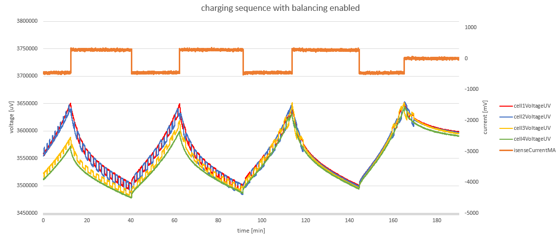
It has been a while since my last question on here. I have since learned to code and have programmed a balancing feature which works(see picture)!

For the next part of the project i want to so an SOC estimation. For this i want to store 2 variables(both in some kind of memory.
the variables would be currentCapacity and maximumCapacity which are of datatype uint32_t (unsigned int, so 4 bytes each). currentCapacity will be updated every 5 minutes and maximumCapacity will be updated when the battery is fully charged or fully discharged.
I want to know the best way to store these values so that when the board is off, the variables are still saved and i know the SOC when i turn the board back on. i found https://community.nxp.com/docs/DOC-340114 , but i also noticed that the FreeMASTER example project has some EEPROM functions already (read and write).
do i need an external device to work with these EEPROM functions or how would i go about setting this up?
kind regards,
Bart
Hi Bart,
Sorry for not getting back to you earlier, I was working on some high priority items.
Yes, the BCC_S32K144_MC33771_SPI_FreeMASTER project uses our FreeMASTER visualization tool to control and display status of MC33771 BCC device.
Best regards,
Tomas
Hi Bart, I'm answering to your both latest comments. RGB LED is controlled by the S32K144 MCU. When it shines red, then you were most probably successful with flashing of the Monitoring or FreeMaster application. As written in the PDF documentations for these examples (located inside the example folders), red LED means an error (in general), you can debug the cause of the error. Most probably, the error is caused by a wrong HW connection of the boards. Please read carefully the PDF documentation related to the example you would like to try. Everything related to the example is written there.
Regarding the FreeMASTER application, you are right that MCUXpresso SDK supports FreeMASTER communication. However, our BCC_S32K144_MC33771_FreeMASTER example also does.
Best Regards,
Jan
Dear Jan,
I finally have a working connection between the freemaster example project and the S32K. Problem was that i did not measure the connections of the small jumper resistors after resoldering them, two of them were not soldered properly. The voltage values are now displayed correctly and i can start programming the balancing and SOC features for my graduation project.
Although i am happy that the connection works, i noticed that when i enable balancing by with functions BCC_CB_Enable and BCC_CB_SetIndividual, the voltages drop but the status of the balancing registers is not shown in the cell balancing section of the freemaster application. So i have no way of really knowing which cell is being balanced. Is there an easy way to get this balancing status visible on the freemaster application?
also i have a question about the coding of the balancing feature. Is it correct that i should make a piece of code that compares all the cell voltages and if the difference between highest and lowest voltage reaches a set threshold balancing should be enabled on the highest voltage cell. I could not find anything on stack overflow about comparing more than 3 values so i might be doing something wrong. Again, i am very new to embedded systems and eager to learn.
Thanks again for your help.
Kind regards,
Bart van Beuningen
Graduate intern at Ebusco
Hi Bart,
regarding the implementation of the cell balancing feature: You are right. MC33771/2 devices can only turn on the balancing for a configurable amount of time. There is no voltage comparison in the device. Therefore, MCU itself must recognize, which cells need balancing. For more than 3 values, you should implement some suitable cycle. You can also try to start with some sorting algorithm (Bubble sort, Merge sort, Quick sort, etc.). You'll find a lot of their implementations online.
You are right that you don't see the finished cell balancing on the left side of the app. However, you are able to check it in the "Status" tab via bits dedicated to CB_Timeout for each cell.
The goal of the FreeMASTER example app was not to cover all the BCC functionality. E.g. Timeout can be set for each cell separately in the device. In the FreeMASTER example, the same timeout is used for all cells. If you want, you can extend the example as you want.
Best regards,
Jan
Dear Jan,
I have made a good start on my first function and i'm still learning a lot!
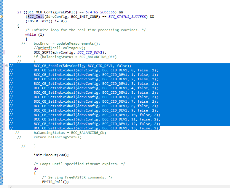
Here is a picture of my function:

it still needs a lot of work, but i am now just fiddling around with enabling the cell balancing.
as you can see in the function, it enables the balancing on highestCell which is currently set to 1(cell 2).
this function is then called in the main function like so:

and after running this code, the voltage of cell 2 drops like expected(i charged cell 2 a bit to test the balancing feature).
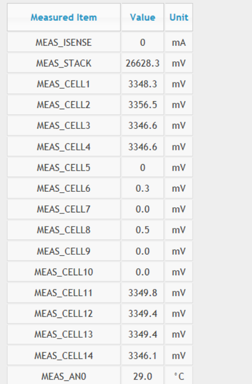
though something is not right, cell 2 drops but cell 1 and 3 rise in voltage which is weird, right?
balancing off:

balancing on(by my function):

Can you tell my why cell 1 and 2 are rising in voltage? Is this expected behavior?
Note that when i connect the kl25z and turn on the balancing manually via the evalGUI, it reacts the same way(so it might be a hardware issue?).
kind regards,
Bart van Beunignen
Dear Tomas,
thanks again for the help, however i am running into some problems.
i tried following the S32K 144EVB quickstart guide, but instead of the blinking RBG led i have a constant red light. this migt be due to the fact that i've been trying to build the BCC_S32K144_Monitoring_Diagnostics project.
then when i continue with the guide, the freemaster application does not recognize the device.
so i tried updating the openSDA firmware, but now the SDA_INFO says the installed application is: PEMicro S32K148EVB-Q144 at version 1.22 and it was PEMicro EVB-S32K144 at version 1.19 at first.
is there any way to completely reset the S32K 144EVB to factory settings? i've tried to get it to work all morning but i think i'm stuck in a loop of trying over and over again...
thanks again for your time, and stay safe during these weird times.
kind regards,
Bart van Beuningen
okay, looking at the demo code i can't find any balancing lines...
i hope that there is anybode that can help me build a balancing function, starting off with just voltage balancing.
i did manage to change the fault masks and ctx_OVUV masks on startup though.


