
- Forums
- Product Forums
- General Purpose MicrocontrollersGeneral Purpose Microcontrollers
- i.MX Forumsi.MX Forums
- QorIQ Processing PlatformsQorIQ Processing Platforms
- Identification and SecurityIdentification and Security
- Power ManagementPower Management
- Wireless ConnectivityWireless Connectivity
- RFID / NFCRFID / NFC
- Advanced AnalogAdvanced Analog
- Neural Processing UnitsNeural Processing Units
- MCX Microcontrollers
- S32G
- S32K
- S32V
- MPC5xxx
- Other NXP Products
- S12 / MagniV Microcontrollers
- Powertrain and Electrification Analog Drivers
- Sensors
- Vybrid Processors
- Digital Signal Controllers
- 8-bit Microcontrollers
- ColdFire/68K Microcontrollers and Processors
- PowerQUICC Processors
- OSBDM and TBDML
- S32M
- S32Z/E
-
- Solution Forums
- Software Forums
- MCUXpresso Software and ToolsMCUXpresso Software and Tools
- CodeWarriorCodeWarrior
- MQX Software SolutionsMQX Software Solutions
- Model-Based Design Toolbox (MBDT)Model-Based Design Toolbox (MBDT)
- FreeMASTER
- eIQ Machine Learning Software
- Embedded Software and Tools Clinic
- S32 SDK
- S32 Design Studio
- GUI Guider
- Zephyr Project
- Voice Technology
- Application Software Packs
- Secure Provisioning SDK (SPSDK)
- Processor Expert Software
- Generative AI & LLMs
-
- Topics
- Mobile Robotics - Drones and RoversMobile Robotics - Drones and Rovers
- NXP Training ContentNXP Training Content
- University ProgramsUniversity Programs
- Rapid IoT
- NXP Designs
- SafeAssure-Community
- OSS Security & Maintenance
- Using Our Community
-
- Cloud Lab Forums
-
- Knowledge Bases
- ARM Microcontrollers
- i.MX Processors
- Identification and Security
- Model-Based Design Toolbox (MBDT)
- QorIQ Processing Platforms
- S32 Automotive Processing Platform
- Wireless Connectivity
- CodeWarrior
- MCUXpresso Suite of Software and Tools
- MQX Software Solutions
- RFID / NFC
- Advanced Analog
- Neural Processing Units
-
- NXP Tech Blogs
- Home
- :
- モデルベース・デザイン・ツールボックス(MBDT)
- :
- モデルベース・デザイン・ツールボックス(MBDT)
- :
- Re: s32k144 pmsm closed loop - sine cosine encoder interfacing
s32k144 pmsm closed loop - sine cosine encoder interfacing
- RSS フィードを購読する
- トピックを新着としてマーク
- トピックを既読としてマーク
- このトピックを現在のユーザーにフロートします
- ブックマーク
- 購読
- ミュート
- 印刷用ページ
- 新着としてマーク
- ブックマーク
- 購読
- ミュート
- RSS フィードを購読する
- ハイライト
- 印刷
- 不適切なコンテンツを報告
Hello
I am trying to interface nxp pmsm closed loop model with sine cosine encoder present in my motor and get the rotor postion data visualized in freemaster.
I am able to add the variables to the freemaster but it is not changing when i rotate the motor.
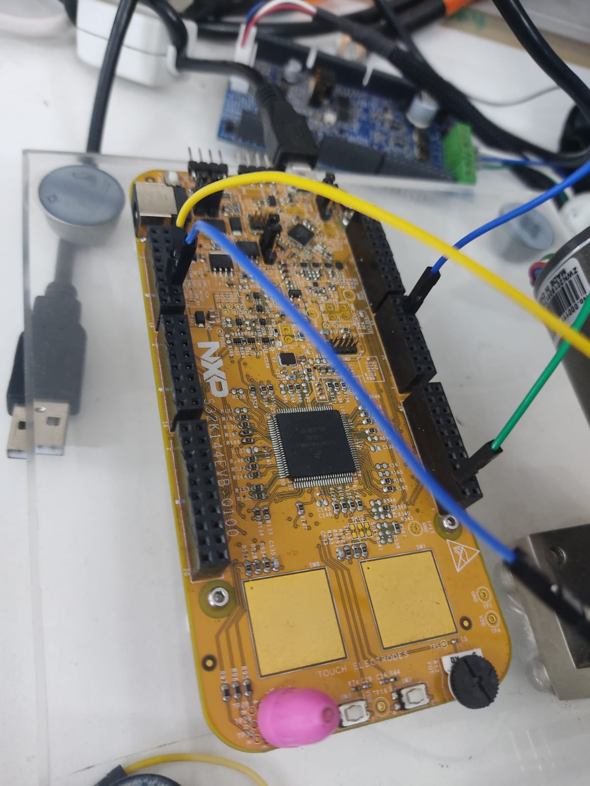
i ll add some pics of my setup and the slx file. Can anyone help me with interfacing the encoder with the s32k and display the results in freemaster . Thanks
the sine cosine encoder has 4 pin outs ( sine cosine 5v and GND)
i have connected the sine and cosine pins with the respective adc pins ( here it is PTD2 and PTD3)
Is there anything i should change in the matlab model to get it working with free master?
Thanks
解決済! 解決策の投稿を見る。
- 新着としてマーク
- ブックマーク
- 購読
- ミュート
- RSS フィードを購読する
- ハイライト
- 印刷
- 不適切なコンテンツを報告
Hi Sriram,
Here is your model updated to read ADCs for the CoSine resolver. Try to start from this model and add incrementally data from your resolver to replace the default hall resolver.
Please let me know if it works.
Best regards,
Adrian
- 新着としてマーク
- ブックマーク
- 購読
- ミュート
- RSS フィードを購読する
- ハイライト
- 印刷
- 不適切なコンテンツを報告
Man I wish I knew this stuff! I'm stuck with a Kelly kbs trying to turn a pmsm with encoders . My controller only accepts hall signal any suggestions?
- 新着としてマーク
- ブックマーク
- 購読
- ミュート
- RSS フィードを購読する
- ハイライト
- 印刷
- 不適切なコンテンツを報告
- 新着としてマーク
- ブックマーク
- 購読
- ミュート
- RSS フィードを購読する
- ハイライト
- 印刷
- 不適切なコンテンツを報告
- 新着としてマーク
- ブックマーク
- 購読
- ミュート
- RSS フィードを購読する
- ハイライト
- 印刷
- 不適切なコンテンツを報告
- 新着としてマーク
- ブックマーク
- 購読
- ミュート
- RSS フィードを購読する
- ハイライト
- 印刷
- 不適切なコンテンツを報告
Hello Sriram,
In order to visualize a variable, used in the MBDT project, in FreeMaster you have to declare it as "volatile". To do that you have to click on those three gray rectangles on the right side down on your work screen. There will pop up a few small square windows like in the photo. Then on the downside will appear a collapsed window named "Code Mappings - Component Interface", click on that, and will raise a window, click on the "Data Stores" tab, and here you will have to find your variable name on the left side, and on the right side, you have to select class of respective variable as "volatile". The build the project and you can add the variable to variable watch in FreeMaster after selecting the latest binary file.
Best regards,
Adrian
- 新着としてマーク
- ブックマーク
- 購読
- ミュート
- RSS フィードを購読する
- ハイライト
- 印刷
- 不適切なコンテンツを報告
Thanks fr the reply sir , I got the variables in the watch by making the code optimization as minimum. But the issue is i'm not able to get a reading from the adc pins (sine cosine - ptd 2 and ptd 3) when i try to view them in oscilloscope in freemaster. it is either stuck at 0 or is at a random value. I want to see the theta variation when i rotate the shaft of the motor. In the matlab model , Theta_EST should output the theta value but in freemaster it is not varying with motor rotation . Is there anything wrong with the matlab model or should i do anything different to get the position value in free master
thanks
ps - im using the matlab model sent by you sir @adriantudor
- 新着としてマーク
- ブックマーク
- 購読
- ミュート
- RSS フィードを購読する
- ハイライト
- 印刷
- 不適切なコンテンツを報告
Hi Sriram,
If you are using the model that you posted here, then you must be aware that ADC readings are triggered by the PDB module which is also triggered by PWM. That means, the ADC is functional only when the motor is running and if you turn the shaft of the motor with your hand, the ADC will not read anything because it's not triggered even if the CoSine encoder is functional. My recommendation is to remove the "speed feedback" that you feed in "SlowLoopControl" block and feed that with the default block. That means you should use the default motor with the default Hall sensors, but you will have to attach somehow (if it's possible) the cosine encoder to the motor shaft. And you can still use your added blocks for the cosine encoder to monitor and debug the cosine encoder.
Let me know if that works.
Best regards,
Adrian
- 新着としてマーク
- ブックマーク
- 購読
- ミュート
- RSS フィードを購読する
- ハイライト
- 印刷
- 不適切なコンテンツを報告
Ok sir will try that