
- Forums
- Product Forums
- General Purpose MicrocontrollersGeneral Purpose Microcontrollers
- i.MX Forumsi.MX Forums
- QorIQ Processing PlatformsQorIQ Processing Platforms
- Identification and SecurityIdentification and Security
- Power ManagementPower Management
- Wireless ConnectivityWireless Connectivity
- RFID / NFCRFID / NFC
- Advanced AnalogAdvanced Analog
- Neural Processing UnitsNeural Processing Units
- MCX Microcontrollers
- S32G
- S32K
- S32V
- MPC5xxx
- Other NXP Products
- S12 / MagniV Microcontrollers
- Powertrain and Electrification Analog Drivers
- Sensors
- Vybrid Processors
- Digital Signal Controllers
- 8-bit Microcontrollers
- ColdFire/68K Microcontrollers and Processors
- PowerQUICC Processors
- OSBDM and TBDML
- S32M
- S32Z/E
-
- Solution Forums
- Software Forums
- MCUXpresso Software and ToolsMCUXpresso Software and Tools
- CodeWarriorCodeWarrior
- MQX Software SolutionsMQX Software Solutions
- Model-Based Design Toolbox (MBDT)Model-Based Design Toolbox (MBDT)
- FreeMASTER
- eIQ Machine Learning Software
- Embedded Software and Tools Clinic
- S32 SDK
- S32 Design Studio
- GUI Guider
- Zephyr Project
- Voice Technology
- Application Software Packs
- Secure Provisioning SDK (SPSDK)
- Processor Expert Software
- Generative AI & LLMs
-
- Topics
- Mobile Robotics - Drones and RoversMobile Robotics - Drones and Rovers
- NXP Training ContentNXP Training Content
- University ProgramsUniversity Programs
- Rapid IoT
- NXP Designs
- SafeAssure-Community
- OSS Security & Maintenance
- Using Our Community
-
- Cloud Lab Forums
-
- Knowledge Bases
- ARM Microcontrollers
- i.MX Processors
- Identification and Security
- Model-Based Design Toolbox (MBDT)
- QorIQ Processing Platforms
- S32 Automotive Processing Platform
- Wireless Connectivity
- CodeWarrior
- MCUXpresso Suite of Software and Tools
- MQX Software Solutions
- RFID / NFC
- Advanced Analog
- Neural Processing Units
-
- NXP Tech Blogs
- Home
- :
- モデルベース・デザイン・ツールボックス(MBDT)
- :
- モデルベース・デザイン・ツールボックス(MBDT)
- :
- SPI configuration MODEL based design tool box- 32 bit instruction (SIMULINK)
SPI configuration MODEL based design tool box- 32 bit instruction (SIMULINK)
- RSS フィードを購読する
- トピックを新着としてマーク
- トピックを既読としてマーク
- このトピックを現在のユーザーにフロートします
- ブックマーク
- 購読
- ミュート
- 印刷用ページ
- 新着としてマーク
- ブックマーク
- 購読
- ミュート
- RSS フィードを購読する
- ハイライト
- 印刷
- 不適切なコンテンツを報告
Hi,
I am having problems setting the word length of the SPI channel 0 buffer to 32 bits from the default 8 bits it comes in. When I do via S32 config studio. The clock is stuck on low as seen on the logic analyzer, although the data I am writing is unit8 at that point.
When I change the data I am writing to the buffer to uint32 from uint8 the model wouldn't compile because the SPI block is expecting uint8 even after I've changed it to 32.,
regards.
So I guess my question is can the SPI be configured for 32 bit word length,
btw my reference examples are: Asynchronous polling Master and Asynchronous Interrupt Master
from the Library browser in Simulink
thanks
解決済! 解決策の投稿を見る。
- 新着としてマーク
- ブックマーク
- 購読
- ミュート
- RSS フィードを購読する
- ハイライト
- 印刷
- 不適切なコンテンツを報告
Hi @kamalwolly ,
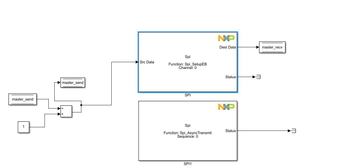
If you click on the 'Output Port 1' link in the error message, the Dest Data output of the SPI block will be highlighted in red. So, this error states that the SPI block will output a one dimensional vector with 4 elements, while the data store memory block that keeps the received data is a one dimensional vector with 1 element.
The SPI block sets the transfer width according to its input, therefore, for also receiving 32 bits data, you need to do the same setting on the recv data store memory block (configure it as an array with 4 uint8 data type values).
As for the debugger, the P&E micro Multilink Universal should work.
Regards,
Irina
- 新着としてマーク
- ブックマーク
- 購読
- ミュート
- RSS フィードを購読する
- ハイライト
- 印刷
- 不適切なコンテンツを報告
Hi @kamalwolly
SPI can be configured for 32 bits word length, and the update you made in the S32 Configuration Tools project (setting the channel's data width to 32) is right.
Now, in Simulink, for writing 32 bits to the buffer, you need to provide the data as an array of uint8 values. In this particular case, you would need 4 values (to get the 32 bits in total). I have attached a screenshot with the data store memory block settings.
Hope this helps,
Irina
- 新着としてマーク
- ブックマーク
- 購読
- ミュート
- RSS フィードを購読する
- ハイライト
- 印刷
- 不適切なコンテンツを報告
New error, the SPI block is expecting a 1 dimensional vector with 1 element and the Memory store is sending a one dimensional vector with 4 elements hence data mismatch, Attached is the error and the block that I'm using to send the information to the SPI buffer
quick side question, the onboard debugger usb on my board ripped off, I want to get an external debugger that still keeps the Simulink to S32K3 workflow with no intermediaries.
below is an external debugger based on the one on the S32k3 eval-board. looking to purchase this. does NXP have any suggestions for an external debugger that integrates with the MBDT. and would the external debugger from P& E micro work
Multilink Debug Probes | Debug Probes for many ARM and 8-/16-/32-bit devices | PEmicro
- 新着としてマーク
- ブックマーク
- 購読
- ミュート
- RSS フィードを購読する
- ハイライト
- 印刷
- 不適切なコンテンツを報告
Hi @kamalwolly ,
If you click on the 'Output Port 1' link in the error message, the Dest Data output of the SPI block will be highlighted in red. So, this error states that the SPI block will output a one dimensional vector with 4 elements, while the data store memory block that keeps the received data is a one dimensional vector with 1 element.
The SPI block sets the transfer width according to its input, therefore, for also receiving 32 bits data, you need to do the same setting on the recv data store memory block (configure it as an array with 4 uint8 data type values).
As for the debugger, the P&E micro Multilink Universal should work.
Regards,
Irina