
- Forums
- Product Forums
- General Purpose MicrocontrollersGeneral Purpose Microcontrollers
- i.MX Forumsi.MX Forums
- QorIQ Processing PlatformsQorIQ Processing Platforms
- Identification and SecurityIdentification and Security
- Power ManagementPower Management
- Wireless ConnectivityWireless Connectivity
- RFID / NFCRFID / NFC
- Advanced AnalogAdvanced Analog
- Neural Processing UnitsNeural Processing Units
- MCX Microcontrollers
- S32G
- S32K
- S32V
- MPC5xxx
- Other NXP Products
- S12 / MagniV Microcontrollers
- Powertrain and Electrification Analog Drivers
- Sensors
- Vybrid Processors
- Digital Signal Controllers
- 8-bit Microcontrollers
- ColdFire/68K Microcontrollers and Processors
- PowerQUICC Processors
- OSBDM and TBDML
- S32M
- S32Z/E
-
- Solution Forums
- Software Forums
- MCUXpresso Software and ToolsMCUXpresso Software and Tools
- CodeWarriorCodeWarrior
- MQX Software SolutionsMQX Software Solutions
- Model-Based Design Toolbox (MBDT)Model-Based Design Toolbox (MBDT)
- FreeMASTER
- eIQ Machine Learning Software
- Embedded Software and Tools Clinic
- S32 SDK
- S32 Design Studio
- GUI Guider
- Zephyr Project
- Voice Technology
- Application Software Packs
- Secure Provisioning SDK (SPSDK)
- Processor Expert Software
- Generative AI & LLMs
-
- Topics
- Mobile Robotics - Drones and RoversMobile Robotics - Drones and Rovers
- NXP Training ContentNXP Training Content
- University ProgramsUniversity Programs
- Rapid IoT
- NXP Designs
- SafeAssure-Community
- OSS Security & Maintenance
- Using Our Community
-
- Cloud Lab Forums
-
- Knowledge Bases
- ARM Microcontrollers
- i.MX Processors
- Identification and Security
- Model-Based Design Toolbox (MBDT)
- QorIQ Processing Platforms
- S32 Automotive Processing Platform
- Wireless Connectivity
- CodeWarrior
- MCUXpresso Suite of Software and Tools
- MQX Software Solutions
- RFID / NFC
- Advanced Analog
- Neural Processing Units
-
- NXP Tech Blogs
- Home
- :
- モデルベース・デザイン・ツールボックス(MBDT)
- :
- モデルベース・デザイン・ツールボックス(MBDT)
- :
- DIO Configuration not setting output
DIO Configuration not setting output
- RSS フィードを購読する
- トピックを新着としてマーク
- トピックを既読としてマーク
- このトピックを現在のユーザーにフロートします
- ブックマーク
- 購読
- ミュート
- 印刷用ページ
DIO Configuration not setting output
- 新着としてマーク
- ブックマーク
- 購読
- ミュート
- RSS フィードを購読する
- ハイライト
- 印刷
- 不適切なコンテンツを報告
Hello,
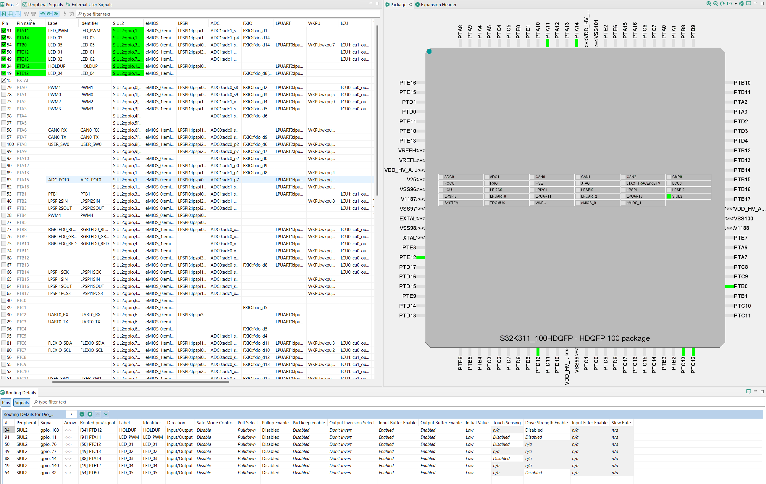
This is my first NXP Project using MBDT. I have the S32K311[NHTOMPAST] on a custom PCB that I am attempting to validate. There are a few output pins attached to LEDs I'd like to see turn on/off but have had mostly poor results; the pins in question are:
"HOLDUP" = PTD12 (has LED attached)
"LED_PWM" = PTA11 (should work as digital gpio, ignore tha PWM in the name)
"LED_01" = PTC12
"LED_02" = PTC13
"LED_03" = PTA14
"LED_04" = PTE12
"LED_05" = PTB0
Yesterday, in a configuration I have since lost, I had HOLDUP, LED1, and LED2 turning on, so I believe they are connected electrically correctly. Interestingly enough, when I would attempt to drive LED3-5 it would turn on LED2. I believe that was a configuration issue, but I no longer have it.
The configuration attached, from my knowledge, does nothing with my model. I am simply attempting to turn on the LEDs and keep them on. I started with an example configuration, added my pins, and deleted the ones I was not using (deleted PWMs, CAN, SPI, etc as I have other pins connected to hardware on this PCB... relays were cycling at a very high frequency so I tried my best to remove them).
After hours of fixing errors related to the things I deleted, I can build my model and flash the board. The board has a very faint buzzing sound (nothing like the relays) which makes me think something unintended is occurring. The LEDs do not turn on. I have looked around the hardware settings, configuration settings, model settings, and the simulink blocks and I have run out of ideas.
I presume the issues are software related, although this is a test of the first PCB made. There is a chance the hardware has an issue, but I'd like to proceed thinking this is a software problem.
Any help is appreciated, I've also attached images if it makes it easier to review. Also note, I've attempted setting my outputs as input/outputs towards the end of my day- neither worked. I apologize for the mess of files, I started with EEETEst.mex but changed a setting in my hardware settings, it now generates a new .mex file when I build.
- 新着としてマーク
- ブックマーク
- 購読
- ミュート
- RSS フィードを購読する
- ハイライト
- 印刷
- 不適切なコンテンツを報告
Hi, @CCaruana,
Thank you for your interest into Model-Based Design Toolbox for S32K3.
First of all, the fact that your configuration with the model name is no longer generated is because you tried to use the referenced configuration functionality. This is a more complex functionality that allows you to share a configuration with multiple models (more details here). But this is not your case. To reset the location to the default value, please run the attached restoreRefConfigLocation.p script, by right-clicking and running, when you have the Simulink model open. This way you will have the default value and you will no longer use this functionality.

Secondly, the pin configuration you mentioned is correct, if the custom PCB is correctly configured from a hardware point of view, it should work. You can test the output of each pin after running the attached example and see the current behavior.
It is impossible for me to test on the board, since you have a custom board, but from the checks made in the configuration project, things seem fine when it comes to pins.
Let us know if you make progress or if you encounter other difficulties.
Best regards,
Dragos