
- Forums
- Product Forums
- General Purpose MicrocontrollersGeneral Purpose Microcontrollers
- i.MX Forumsi.MX Forums
- QorIQ Processing PlatformsQorIQ Processing Platforms
- Identification and SecurityIdentification and Security
- Power ManagementPower Management
- Wireless ConnectivityWireless Connectivity
- RFID / NFCRFID / NFC
- Advanced AnalogAdvanced Analog
- Neural Processing UnitsNeural Processing Units
- MCX Microcontrollers
- S32G
- S32K
- S32V
- MPC5xxx
- Other NXP Products
- S12 / MagniV Microcontrollers
- Powertrain and Electrification Analog Drivers
- Sensors
- Vybrid Processors
- Digital Signal Controllers
- 8-bit Microcontrollers
- ColdFire/68K Microcontrollers and Processors
- PowerQUICC Processors
- OSBDM and TBDML
- S32M
- S32Z/E
-
- Solution Forums
- Software Forums
- MCUXpresso Software and ToolsMCUXpresso Software and Tools
- CodeWarriorCodeWarrior
- MQX Software SolutionsMQX Software Solutions
- Model-Based Design Toolbox (MBDT)Model-Based Design Toolbox (MBDT)
- FreeMASTER
- eIQ Machine Learning Software
- Embedded Software and Tools Clinic
- S32 SDK
- S32 Design Studio
- GUI Guider
- Zephyr Project
- Voice Technology
- Application Software Packs
- Secure Provisioning SDK (SPSDK)
- Processor Expert Software
- Generative AI & LLMs
-
- Topics
- Mobile Robotics - Drones and RoversMobile Robotics - Drones and Rovers
- NXP Training ContentNXP Training Content
- University ProgramsUniversity Programs
- Rapid IoT
- NXP Designs
- SafeAssure-Community
- OSS Security & Maintenance
- Using Our Community
-
- Cloud Lab Forums
-
- Knowledge Bases
- ARM Microcontrollers
- i.MX Processors
- Identification and Security
- Model-Based Design Toolbox (MBDT)
- QorIQ Processing Platforms
- S32 Automotive Processing Platform
- Wireless Connectivity
- CodeWarrior
- MCUXpresso Suite of Software and Tools
- MQX Software Solutions
- RFID / NFC
- Advanced Analog
- Neural Processing Units
-
- NXP Tech Blogs
MPC5748G stop mode and wakeup

Hi,
My project now is using MPC5748G's Sleep mode and Wakeup mode,and there is a lp_stop example in the MPC5748G demo(S32 Design Studio's demo).In the MPC5748GRM, the current is about 11 mA in the Sleep mode,but there is a differece in my testing result. I have a MPC5748GLCEVB and a programmed DC.
First, I conncted EVB's power supply input(P12,1--5V,3--GND) to the DC(5V,1.5A).
Second, I downloaded the lp_stop project to the EVB using PE and S32 IDE.
But I found the current from the programmed DC window changed between 114mA (Sleep mode?)to 121mA(Wakeup mode?), why the current is not about 11 mA.
Thank you!

 martin_kovar
Hello,
I downloaded the project you had mentioned into the microcontroller and I measured following values:
If microcontroller is waked up and it executes NOP instructions in while loop, I measured about 170mA.
If microcontroller is in stop mode, I measured about 8mA.
From your description it looks like the micro is not in STOP mode. Did you measure it with debug probe? If yes, could you please try to measure it without debug probe?
Where did you measure the current?
Regards,
Martin
Hi,Martin Kovar
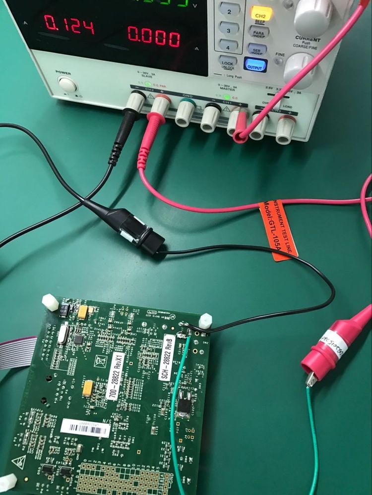
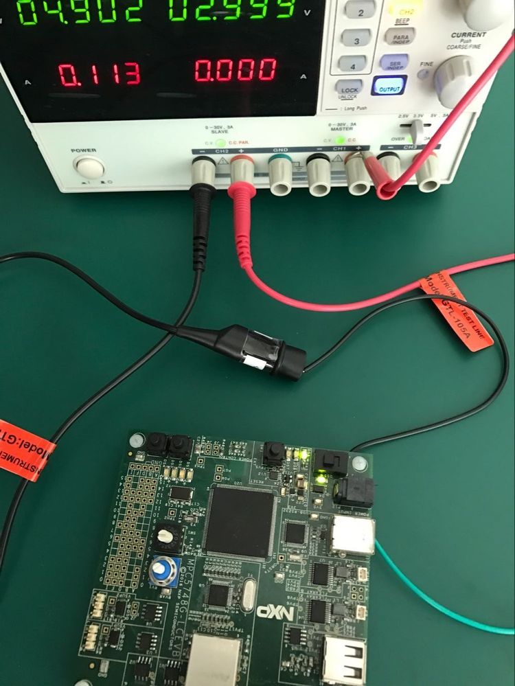
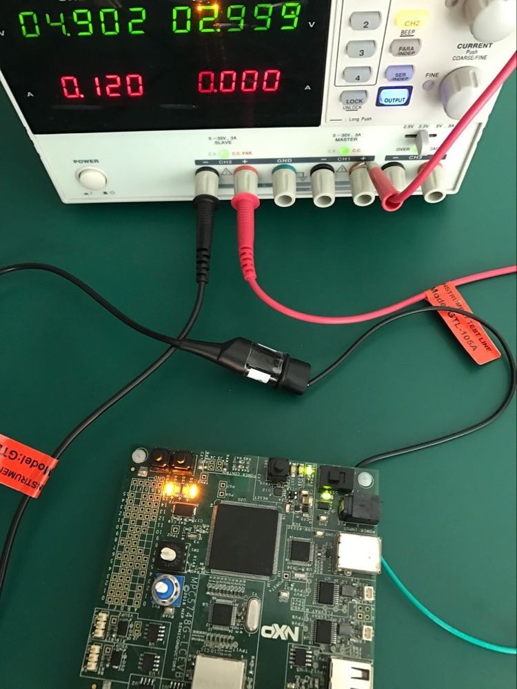
Here are my pictures : The EVB's Power supply pins(1--5V,3--GND) connected the DC, I can measure
the EVB's current. Is this the microcontroller's current? If not ,how can I measure the current.
My project code is below:
/* FILE NAME: lp_stop_Z4_1.c COPYRIGHT (c) NXP Semiconductors 2016 */
/* All Rights Reserved */
/* PLATFORM: DEVKIT-MPC5748G */
/* DESCRIPTION: Low power STOP mode is entered and exits based on RTC timeout*/
/* While in RUN mode a pin to an DS4 LED on NXP EVB is turned */
/* and stop mode is entered. */
/* At RTC timeout(after 0.1s), the stop mode is exited and */
/* DS4 LED is turned off and again goes to the stop mode. */
/* Again at RTC timeout(after 0.9s), the stop mode is exited */
/* and the loop is repeated */
/*****************************************************************************/
/* REV AUTHOR DATE DESCRIPTION OF CHANGE */
/* --- ----------- ---------- --------------------- */
/* 1.0 SM 29 Jul 2014 Initial Version */
/* 1.1 SM 07 Jan 2015 Minor code re-organization */
/* 1.2 SM 12 Feb 2015 Removed unrequired SIUL ME_PCTL code */
/* 1.3 K Shah 15 Mar 2016 Porting to S32DS */
/*****************************************************************************/
#include "derivative.h" /* include peripheral declarations */
#include "project.h"
#include "mode.h"
#define KEY_VALUE1 0x5AF0ul
#define KEY_VALUE2 0xA50Ful
extern void xcptn_xmpl(void);
void peri_clock_gating (void); /* ConfigureS gating/enabling peripheral(WKPU, RTC-API) clocks */
void hw_init(void)
{
#if defined(DEBUG_SECONDARY_CORES)
uint32_t mctl = MC_ME.MCTL.R;
#if defined(TURN_ON_CPU1)
/* enable core 1 in all modes */
MC_ME.CCTL[2].R = 0x00FE;
/* Set Start address for core 1: Will reset and start */
MC_ME.CADDR[2].R = 0x11d0000 | 0x1;
#endif
#if defined(TURN_ON_CPU2)
/* enable core 2 in all modes */
MC_ME.CCTL[3].R = 0x00FE;
/* Set Start address for core 2: Will reset and start */
MC_ME.CADDR[3].R = 0x13a0000 | 0x1;
#endif
MC_ME.MCTL.R = (mctl & 0xffff0000ul) | KEY_VALUE1;
MC_ME.MCTL.R = mctl; /* key value 2 always from MCTL */
#endif /* defined(DEBUG_SECONDARY_CORES) */
}
__attribute__ ((section(".text")))
/************************************ Main ***********************************/
int main(void)
{
uint32_t i = 0;
xcptn_xmpl (); /* Configures and Enables Interrupts */
peri_clock_gating(); /* Configures gating/enabling peripheral(WKPU, RTC-API) clocks for modes*/
/* Configuration occurs after mode transition */
system160mhz();
/* Sets clock dividers= max freq, calls PLL_160MHz function which:
MC_ME.ME: enables all modes for Mode Entry module
Connects XOSC to PLL
PLLDIG: LOLIE=1, PLLCAL3=0x09C3_C000, no sigma delta, 160MHz
MC_ME.DRUN_MC: configures sysclk = PLL
Mode transition: re-enters DRUN mode
*/
/* Additional mode configurations for STOP, RUN3 modes & enter RUN3 mode: */
MC_ME.RUN_MC[3].R = 0x001F0090; /* MVRON=1 FLAON=RUN SIRCON=1 FIRCON=1 sysclk=FIRC */
MC_ME.STOP_MC.R = 0x00130090; /* MVRON=1 FLAON=RUN SIRCON=1 FIRCON=1 sysclk=FIRC */
MC_ME.MCTL.R = 0x70005AF0; /* Enter RUN3 Mode & Key */
MC_ME.MCTL.R = 0x7000A50F; /* Enter RUN3 Mode & Inverted Key */
while (MC_ME.GS.B.S_MTRANS) {} /* Wait for RUN3 mode transition to complete */
/* Note: could wait here using timer and/or I_TC IRQ */
while(MC_ME.GS.B.S_CURRENT_MODE != 7) {} /* Verify RUN3 (0x7) is the current mode */
/* Configure Wake up Unit for low power exit */
WKPU.WIREER.R = 0x00000042; /* Enable rising edge events on RTC, PE[0] */
WKPU.WIFER.R = 0x00000040; /* Enable analog filters - , PE[0] */
WKPU.WRER.R = 0x00000002; /* Enable wake up events for RTC, but not PE[0] */
WKPU.WIPUER.R = 0x000FFFFF; /* Enable WKPU pins pull-ups to stop leakage*/
/* Enable general purpose output that is connected to LED1 on NXP EVB */
//SIUL2.MSCR[PA10].B.OBE = 1; /* Pad PA10 (10): OBE=1. On EVB active low DS4 LED */
SIUL2.MSCR[PG5].B.OBE = 1;//EVB LED
SIUL2.MSCR[PG2].B.OBE = 1; //EVB LED
while(1) {
//SIUL2.GPDO[PA10].R = 0; /* Pad PA10 (10): EVB DS4 LED active low */
SIUL2.GPDO[PG5].R = 0; //EVB LED
SIUL2.GPDO[PG2].R = 0; //EVB LED
RTC.RTCC.R = 0x00000000; /* Clear CNTEN to reset */
RTC.RTCC.R = 0xA0001000; /* CLKSEL = 128KHz SIRC, FRZEN=CNTEN=1*/
RTC.RTCVAL.R = 12800; /* #RTC clocks. Timeout=12.8K/128KHz=0.1 sec*/
WKPU.WISR.R = 0x00000002; /* Clear wake up flag RTC */
enter_STOP_mode(); /* Enter STOP mode */
/* ON STOP MODE EXIT, CODE CONTINUES HERE: */
while(MC_ME.GS.B.S_CURRENT_MODE != 7) {} /* Verify RUN3 (0x7) is current mode */
//SIUL2.GPDO[PA10].R = 1; /* Pad PA10 (10): EVB DS4 LED active low */
SIUL2.GPDO[PG5].R = 1; //EVB LED
SIUL2.GPDO[PG2].R = 1; //EVB LED
RTC.RTCC.R = 0x00000000; /* Clear CNTEN to reset */
RTC.RTCC.R = 0xA0001000; /* CLKSEL = 128KHz SIRC, FRZEN=CNTEN=1*/
RTC.RTCVAL.R = 115200; /* #RTC clocks. Timeout=115.2K/128KHz=0.9 sec*/
WKPU.WISR.R = 0x00000002; /* Clear wake up flag RTC */
enter_STOP_mode (); /* Enter STOP mode */
/* ON STOP MODE EXIT, CODE CONTINUES HERE: */
while(MC_ME.GS.B.S_CURRENT_MODE != 7) {} /* Verify RUN3 (0x7) is current mode */
i++; /* Counter for STOP mode pairs of cycles */
}
return 0;
}
/******************************End of Main ***********************************/
void peri_clock_gating (void) { /* Configures gating/enabling peripheral(WKPU, RTC-API) clocks for modes*/
MC_ME.RUN_PC[0].R = 0x00000000; /* gate off clock for all RUN modes */
MC_ME.RUN_PC[1].R = 0x000000FE; /* Configures peripheral clock for all RUN modes */
MC_ME.RUN_PC[7].R = 0x00000088; /* Run peripheral configuration 7 settings: run in DRUN, RUN3 modes */
MC_ME.LP_PC[7].R = 0x00000400; /* LP peripheral configuration 7 settings: run in STOP */
MC_ME.PCTL[93].R = 0x3F; /* WKPU: select peripheral configuration RUN_PC[7], LP_PC[7] */
MC_ME.PCTL[102].R = 0x3F; /* RTC-API: select peripheral configuration RUN_PC[7], LP_PC[7] */
}
martin_kovar
Hello,
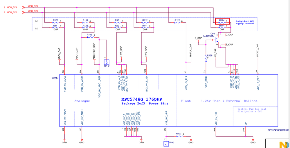
you measure EVB current not microcontroller current. EVB current difference between micro in stop mode and run mode is not the same as current difference measure directly at microcontroller .
Unfortunately, this board is not much suitable for the current measurement. You have to disassemble R124 and connect there the ampere meter. Please see picture below:
Regards,
Martin
Hi,
Thank you.
I followed your's advice:disabled the R124 and connected ampere meter.
I measured the current about 7.9mA, and the led's blinked. But the ampere meter measured the current was still about 7.9mA, it looked like the MCU always enters in the waked up mode and can not enter in RUN3 mode again.
In my opinion, led's blinked showed the MCU waked up. But in yous answer:If microcontroller is waked up and it executes NOP instructions in while loop, I measured about 170mA. I don't understand.
Forgave me for these silly questions.
Best Regards,
Tom_Chen
martin_kovar
Hello Tom,
using this example it is not possible to measure current when microcontroller is in RUN mode and executes some instruction (because example switches microcontroller between RUN and STOP), so I edited the example and I added following code behind system160mhz();
while(1)
{
asm("e_nop");
asm("e_nop");
asm("e_nop");
asm("e_nop");
}
This allowed me to measure current, in RUN mode (when nop instructions were executed, I measured 170mA).
In general, this example is not suitable for current measuring. It will be better to create some example where microcontroller stays in (D)RUN mode (you can accurately measure measure current in D(RUN) mode) and then switch microcontroller to STOP mode using some button and measure the current in STOP mode.
If you have any other questions, please feel free to write me back.
Regards.
Martin
Hi,Martin Kovar
You are right. I can measure the current abou 170mA. I always think the microchip enters stop mode ,
that means all the peripherals shut down , and leds didn't work.
This example shows the code executes while loop,and enters stop mode,the instructions in the while
loop still work.
Best Regards,
Tom_Chen
