- Forums
- Product Forums
- General Purpose MicrocontrollersGeneral Purpose Microcontrollers
- i.MX Forumsi.MX Forums
- QorIQ Processing PlatformsQorIQ Processing Platforms
- Identification and SecurityIdentification and Security
- Power ManagementPower Management
- MCX Microcontrollers
- S32G
- S32K
- S32V
- MPC5xxx
- Other NXP Products
- Wireless Connectivity
- S12 / MagniV Microcontrollers
- Powertrain and Electrification Analog Drivers
- Sensors
- Vybrid Processors
- Digital Signal Controllers
- 8-bit Microcontrollers
- ColdFire/68K Microcontrollers and Processors
- PowerQUICC Processors
- OSBDM and TBDML
- S32M
-
- Solution Forums
- Software Forums
- MCUXpresso Software and ToolsMCUXpresso Software and Tools
- CodeWarriorCodeWarrior
- MQX Software SolutionsMQX Software Solutions
- Model-Based Design Toolbox (MBDT)Model-Based Design Toolbox (MBDT)
- FreeMASTER
- eIQ Machine Learning Software
- Embedded Software and Tools Clinic
- S32 SDK
- S32 Design Studio
- GUI Guider
- Zephyr Project
- Voice Technology
- Application Software Packs
- Secure Provisioning SDK (SPSDK)
- Processor Expert Software
-
- Topics
- Mobile Robotics - Drones and RoversMobile Robotics - Drones and Rovers
- NXP Training ContentNXP Training Content
- University ProgramsUniversity Programs
- Rapid IoT
- NXP Designs
- SafeAssure-Community
- OSS Security & Maintenance
- Using Our Community
-
- Cloud Lab Forums
-
- Knowledge Bases
- ARM Microcontrollers
- i.MX Processors
- Identification and Security
- Model-Based Design Toolbox (MBDT)
- QorIQ Processing Platforms
- S32 Automotive Processing Platform
- Wireless Connectivity
- CodeWarrior
- MCUXpresso Suite of Software and Tools
- MQX Software Solutions
-
- Home
- :
- Product Forums
- :
- MPC5xxx
- :
- MPC5744P Cant connect to MCU via Multilink FX
MPC5744P Cant connect to MCU via Multilink FX
- Subscribe to RSS Feed
- Mark Topic as New
- Mark Topic as Read
- Float this Topic for Current User
- Bookmark
- Subscribe
- Mute
- Printer Friendly Page
MPC5744P Cant connect to MCU via Multilink FX
- Mark as New
- Bookmark
- Subscribe
- Mute
- Subscribe to RSS Feed
- Permalink
- Report Inappropriate Content
Hello,
I would like to ask you for a help with MPC5744P. I have a custom board which I am trying to get working using MPC5744P. Unfortunately, when I am trying to connect to the MCU with PE Multilink Universal FX I am getting an error. (see the attached picture) I inspected the power supplies and every pin is getting the correct voltage (either 3V3 or 1V25). 1V25 is supplied by external voltage regulator and it is at the right voltage. RST pin is pulled up to 3V3 with a 10k resistor and the same is with the POR pin but both of those pins, are pulled by the MCU low at all times. BCTRL pin is also pulled low even when pulled up with 10k to 1V25.
Attached, you can see the configuration of the debug probe in S32 Design Studio.
Why is MCU on purpose pulling the lines low?
Thanks for any ideas in advance.
Best regards,
Tomas
- Mark as New
- Bookmark
- Subscribe
- Mute
- Subscribe to RSS Feed
- Permalink
- Report Inappropriate Content
Hi, it seems familiar to me.
Pay attention to following thread at the very bottom:
https://community.nxp.com/t5/MPC5xxx/MCU-always-in-reset/m-p/1231382
Dont you have PORST and RESET lines interconnected?
- Mark as New
- Bookmark
- Subscribe
- Mute
- Subscribe to RSS Feed
- Permalink
- Report Inappropriate Content
Hi,
thank you for your answer, but both of the lines are pulled up to a 3V3 power supply through a 10k resistor. They are definitely not interconnected. At least when I try measure a resistance between them in off state I get 1 megaOhm.
See the schematic of the board attached, any ideas would be much appreciated.
Best regards,
Tomas
- Mark as New
- Bookmark
- Subscribe
- Mute
- Subscribe to RSS Feed
- Permalink
- Report Inappropriate Content
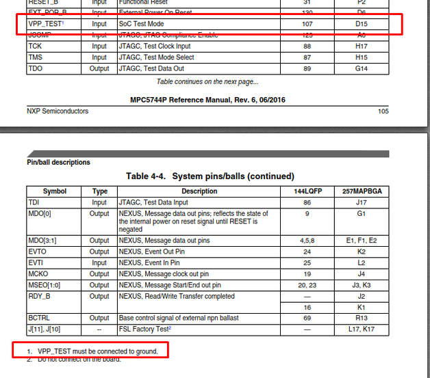
You have a fairly fundamental mistake there.
- Mark as New
- Bookmark
- Subscribe
- Mute
- Subscribe to RSS Feed
- Permalink
- Report Inappropriate Content
Thank you very much for pointing that out. I fixed that, so now the VPP_TEST is tied to GND, but still the same behaviour appears. MCU is not starting, RST and POR pins are held low. So no luck on this front.
Do you have any other ideas/suggestions?
Thanks so much in advance.
Tomas
- Mark as New
- Bookmark
- Subscribe
- Mute
- Subscribe to RSS Feed
- Permalink
- Report Inappropriate Content
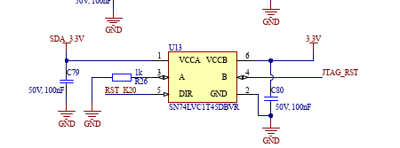
Don't you K20 in reset? Do you have some SW flashed in K20 device? I suppose this may keep MPC5744P in reset
- Mark as New
- Bookmark
- Subscribe
- Mute
- Subscribe to RSS Feed
- Permalink
- Report Inappropriate Content
The K20 was meant to be OpenSDA, but since DAPLink isnt compatible with power architecture, this idea was scraped. Right now, U13 is desoldered, so the JTAG input into the AND gate is pulled permanently high with 10k.
- Mark as New
- Bookmark
- Subscribe
- Mute
- Subscribe to RSS Feed
- Permalink
- Report Inappropriate Content
Have you measure power-up sequence along with PORST and RESET signal?
- Mark as New
- Bookmark
- Subscribe
- Mute
- Subscribe to RSS Feed
- Permalink
- Report Inappropriate Content
Here is the power up sequence. The yellow line is input 3V3 power, green is 1V25 power line, blue is the PORST and orange is the RST line. PORST after the events ends at 138mV, RST ends up at 35mV. Seems like the MCU just doesnt want to start. Any ideas would be very appreciated.
Best regards,
Tomas
- Mark as New
- Bookmark
- Subscribe
- Mute
- Subscribe to RSS Feed
- Permalink
- Report Inappropriate Content
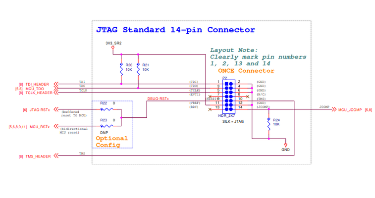
I don't know a reason why don't use standardized JTAG connector, anyway, 3.3V must be used there as on the screenshot below (MPC5644P_DEVKIT), you have there 5V:
What about FAB pin, do you have it connected to the GND? Have you tried POR sequence without connected debugger?
- Mark as New
- Bookmark
- Subscribe
- Mute
- Subscribe to RSS Feed
- Permalink
- Report Inappropriate Content
Hi,
I tried to measure the power up sequence without connected debugger and I got pretty much the same result as with one connected, see below.
I noticed strange behavior on the power off, look at the image attached. When power is being switched off it seems like the MCU at some point releases the RST and PORST pin and then it discharges with the PS as they are pulled up to 3V3 which is yellow on that chart. Which I guess confirms, that MCU is holding these pins down deliberately. I am confused, why is this happening, MCU has the right power and everything.
- Mark as New
- Bookmark
- Subscribe
- Mute
- Subscribe to RSS Feed
- Permalink
- Report Inappropriate Content
EXT_POR is supposed to be pulled-up by 4.7k, but you have there only 1M resistor on the buck regulator.
- Mark as New
- Bookmark
- Subscribe
- Mute
- Subscribe to RSS Feed
- Permalink
- Report Inappropriate Content
I also noticed, that on TDI, TCLK and TMS I have 0,8V DC constantly. When I am trying to load SW (from S32 studio) there is no activity on TCLK (scope is not triggered when set to trip on 1V).
- Mark as New
- Bookmark
- Subscribe
- Mute
- Subscribe to RSS Feed
- Permalink
- Report Inappropriate Content
Hi, it was mainly for space concerns, however it proved to be pain to deal with when debugging so next version will have the standardized connector. The 5V was used mainly for general power up of the board, also because we were not using standardized JTAG, but the 3V3 and 1V25 is made from 5V so CPU should be getting the power it requires.
FAB pin is tied to ground through that switch, the other boot selection pins are tied to 3V3 for now.
The power up sequence is measured without a debugger connected. I will try to measure the power up sequence with the debugger connected.
PS: Last week I also posted another question here on the forums and I have not got an answer for that. Would you mind take a look at that as well?
https://community.nxp.com/t5/MPC5xxx/DEVKIT-MCP5744P-connector-spacing/m-p/1296218#M18510
Thank you so much for you time and help.
Best regards,
Tomas
- Mark as New
- Bookmark
- Subscribe
- Mute
- Subscribe to RSS Feed
- Permalink
- Report Inappropriate Content
BCTRL must be left open.
- Mark as New
- Bookmark
- Subscribe
- Mute
- Subscribe to RSS Feed
- Permalink
- Report Inappropriate Content


