
- Forums
- Product Forums
- General Purpose MicrocontrollersGeneral Purpose Microcontrollers
- i.MX Forumsi.MX Forums
- QorIQ Processing PlatformsQorIQ Processing Platforms
- Identification and SecurityIdentification and Security
- Power ManagementPower Management
- Wireless ConnectivityWireless Connectivity
- RFID / NFCRFID / NFC
- Advanced AnalogAdvanced Analog
- Neural Processing UnitsNeural Processing Units
- MCX Microcontrollers
- S32G
- S32K
- S32V
- MPC5xxx
- Other NXP Products
- S12 / MagniV Microcontrollers
- Powertrain and Electrification Analog Drivers
- Sensors
- Vybrid Processors
- Digital Signal Controllers
- 8-bit Microcontrollers
- ColdFire/68K Microcontrollers and Processors
- PowerQUICC Processors
- OSBDM and TBDML
- S32M
- S32Z/E
-
- Solution Forums
- Software Forums
- MCUXpresso Software and ToolsMCUXpresso Software and Tools
- CodeWarriorCodeWarrior
- MQX Software SolutionsMQX Software Solutions
- Model-Based Design Toolbox (MBDT)Model-Based Design Toolbox (MBDT)
- FreeMASTER
- eIQ Machine Learning Software
- Embedded Software and Tools Clinic
- S32 SDK
- S32 Design Studio
- GUI Guider
- Zephyr Project
- Voice Technology
- Application Software Packs
- Secure Provisioning SDK (SPSDK)
- Processor Expert Software
- Generative AI & LLMs
-
- Topics
- Mobile Robotics - Drones and RoversMobile Robotics - Drones and Rovers
- NXP Training ContentNXP Training Content
- University ProgramsUniversity Programs
- Rapid IoT
- NXP Designs
- SafeAssure-Community
- OSS Security & Maintenance
- Using Our Community
-
- Cloud Lab Forums
-
- Knowledge Bases
- ARM Microcontrollers
- i.MX Processors
- Identification and Security
- Model-Based Design Toolbox (MBDT)
- QorIQ Processing Platforms
- S32 Automotive Processing Platform
- Wireless Connectivity
- CodeWarrior
- MCUXpresso Suite of Software and Tools
- MQX Software Solutions
- RFID / NFC
- Advanced Analog
- Neural Processing Units
-
- NXP Tech Blogs
- Home
- :
- Product Forums
- :
- MPC5xxx
- :
- Re: MPC5743R Flash Erase exception
MPC5743R Flash Erase exception
- Subscribe to RSS Feed
- Mark Topic as New
- Mark Topic as Read
- Float this Topic for Current User
- Bookmark
- Subscribe
- Mute
- Printer Friendly Page
MPC5743R Flash Erase exception

- Mark as New
- Bookmark
- Subscribe
- Mute
- Subscribe to RSS Feed
- Permalink
- Report Inappropriate Content
HI,
According to the MPC5743R data manual, there are a total of 6 256K Code Flash blocks. I can erase the first 3 blocks, but the fourth block erases abnormally. The memory display is as follows:
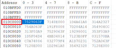
The address 0x010c0000 is the starting address of the fourth block. The data after this address is still the previous programming data and has not been erased and changed to FFFFFFFF
I use a pGetLock function to read the FLASH lock status, the blkLockState is read as zero,It should be 6 256KB Code Flash blocks that are not locked
returnCode = pGetLock(&ssdConfig, C55_BLOCK_256K_FIRST, &blkLockState);
if (C55_OK != returnCode)
{
ErrorTrap(returnCode);
}
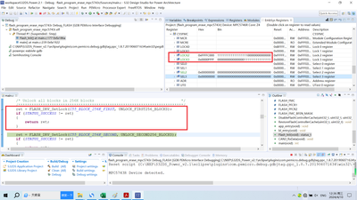
After erasing all FLASH, check the C55FMC register and it will display as follows:

 petervlna
- Mark as New
- Bookmark
- Subscribe
- Mute
- Subscribe to RSS Feed
- Permalink
- Report Inappropriate Content
Hello,
but the fourth block erases abnormally.
I see the block starting with address 0x010c0000 is not erased at all. So no erase was done on this block - 256KB Code Flash block3.
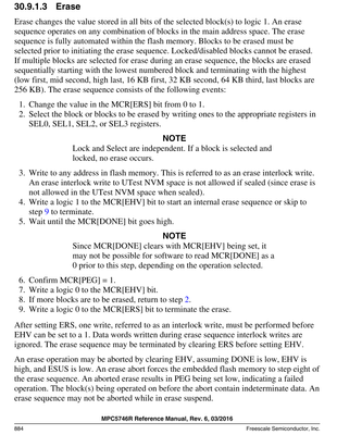
I do not know which driver you have used for these operation but erase is described in details in the reference manual:
Confirm with your driver that you are following mandatory steps for erase.
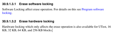
and not that there can be locking:
Best regards,
Peter
- Mark as New
- Bookmark
- Subscribe
- Mute
- Subscribe to RSS Feed
- Permalink
- Report Inappropriate Content
Hello:
I have tried two methods:
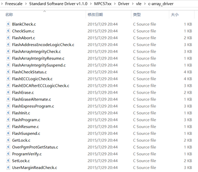
The first method is to use the Standard Software Driver for C55 Flash provided on the NXP official website, as follows:
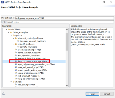
The second method is to modify the routine "flash program erase_mpc5746r" after installing S32DS Power Win32_v2.1 software.
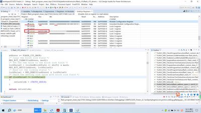
After downloading the program software for simulation testing, it was found that the configuration of the LOCK2 register is the same for both methods after FLASH initialization. Is this register configured correctly? As shown in the figure:
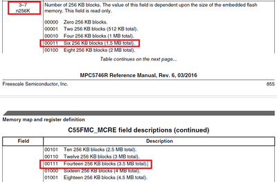
In the MCRE register, there are 5 bits of n256K. I believe that MPC5743R is a 1.5M FLASH, which should be 00011 Six 256 KB blocks (1.5 MB total). However, after observing the simulation, the value of the MCRE register is 00111 Fourteen 256 KB blocks (3.5 MB total)
petervlna
- Mark as New
- Bookmark
- Subscribe
- Mute
- Subscribe to RSS Feed
- Permalink
- Report Inappropriate Content
Hello,
Even if you unlock all blocks, the erase will be done on the blocks that are selected by SELx registers.
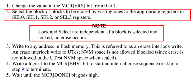
I guess lock is open for full testing of MPC5746R memory range in drivers.
In the MCRE register, there are 5 bits of n256K. I believe that MPC5743R is a 1.5M FLASH, which should be 00011 Six 256 KB blocks (1.5 MB total). However, after observing the simulation, the value of the MCRE register is 00111 Fourteen 256 KB blocks (3.5 MB total)
Since I do not have the MPC5743R device here I assume you are correct.
The MCRE will be common for both versions of MPC574R and 43R. I would not bother with that. I can order MPC5743R to do the tests, but I will probably find the same as you.
Just make sure the blocks you are going to erase are unlocked and correctly set in SEL registers.
There should be no issue in erase unless you have damaged uC.
Best regards,
Peter
- Mark as New
- Bookmark
- Subscribe
- Mute
- Subscribe to RSS Feed
- Permalink
- Report Inappropriate Content
Hello,
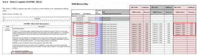
I ran simulation tests in a single step and found that after FLASH initialization, the value of register LOCK2 was 0xFFFFC000. During FLASH erase,
when erasing the first 256K Block, the value of register SEL2 was 0x0000001.
When erasing the second 256K Block, the value of register SEL2 was 0x0000002.
When erasing the third 256K Block, the value of register SEL2 was 0x0000004.
When erasing the fourth 256K Block, the value of register SEL2 was 0x0000008.
When erasing the fifth 256K Block, the value of register SEL2 was 0x00000010.
When the sixth 256K BLOCK is reached, the value of register SEL2 is 0x00000020,
Therefore, this corresponds exactly to six 256KB Code Flash blocks.
The setting operation of ERS and EHV in registers MCR is also normal.
When initializing Lock2, the value of the register is 0XFFFFC000, indicating that 14 256KB Code Flash blocks have been unlocked, which corresponds exactly to the 14 256KB Code Flash blocks of MPC5746R, as shown in the following figure:
And I used two controllers, and the test results were the same.
Do you think my understanding is correct?
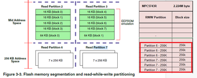
From the diagram below, it can be seen that only Pation 6 can be programmed and erased, while Pation 7 can only be programmed but not erased. Is this related to this configuration?
Thank you!
petervlna
- Mark as New
- Bookmark
- Subscribe
- Mute
- Subscribe to RSS Feed
- Permalink
- Report Inappropriate Content
Hello,
Do you think my understanding is correct?
Your understanding is correct. Since this is phantom device of MPC5746R it contains same flash size, but you can only use what you have paid for. In this case MPC5743R size of flash. Otherwise we do not guarantee functionality.
Best regards,
Peter
- Mark as New
- Bookmark
- Subscribe
- Mute
- Subscribe to RSS Feed
- Permalink
- Report Inappropriate Content
Hello,
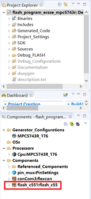
I used the C55 FLASH driver library generated by Processor Expert, and the Processor was configured to use MPC5743R. I only called the driver library functions through routines and did not make any other changes.
Why can't we erase FLASH after address 0x010c0000?
Can you find a development board to help me test it?
Thank you!
petervlna
- Mark as New
- Bookmark
- Subscribe
- Mute
- Subscribe to RSS Feed
- Permalink
- Report Inappropriate Content
Hello,
I have done test in lauterbach IDE for
program:
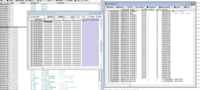
and erase afterwards:
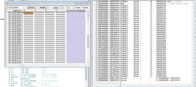
And I see no issue in uC for doing program and erase of that specific block.
Why can't we erase FLASH after address 0x010c0000?
I expect you did not follow reference manual steps for erasing the flash block as I have posted before.
So you used C55 flash driver for which compiler? CW, DIAB or GHS?
Best regards,
Peter
- Mark as New
- Bookmark
- Subscribe
- Mute
- Subscribe to RSS Feed
- Permalink
- Report Inappropriate Content
Hello,
The system configuration I am using is:
Development tool: S32DS-Power-Win32_v2.1
Compiler: powerpc-eabivle-gcc
After the installation of S32DS-Power-Win32_v2.1 is completed, it defaults to this compiler
The driver library I am using is: Standard Software Driver for C55 Flash v1.1.0
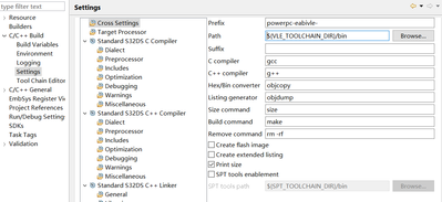
Can you give me your test routine? On my development test board, I test and verify
Thank you!
petervlna
- Mark as New
- Bookmark
- Subscribe
- Mute
- Subscribe to RSS Feed
- Permalink
- Report Inappropriate Content
Hello,
I have used Lauterbach debug IDE to test erase of that location. No code was programmed in micro except one address which I intended to erase.
Furthermore did you pay attention to:
3.3 Notes and Limitations
Please pay attention to the following items while using the SSD:
1. Interrupt vectors; service routines; and application code executed while there is an erase or program in progress CANNOT reside in flash partitions that are targeted for program or erase.
Are you using the demo code from C55 or you embed driver to your SW?
Best regards,
Peter
- Mark as New
- Bookmark
- Subscribe
- Mute
- Subscribe to RSS Feed
- Permalink
- Report Inappropriate Content
Hello,

I have embedded SSD C55 into my program. Can you provide me with a demo code for C55?
My bootloader program starts from 0x00F9C400, and my application starts from 0x010000000. During the testing process, only the bootloader program was used to test the 8-byte programming and erasing of FLASH addresses for different application programs.
Thank you!
petervlna
- Mark as New
- Bookmark
- Subscribe
- Mute
- Subscribe to RSS Feed
- Permalink
- Report Inappropriate Content
Hello,
It is part of C55 driver.
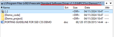
You can check the erase procedure I have posted from Reference manual and compare it to the one you are using.
Best regards,
Peter
