- Forums
- Product Forums
- General Purpose MicrocontrollersGeneral Purpose Microcontrollers
- i.MX Forumsi.MX Forums
- QorIQ Processing PlatformsQorIQ Processing Platforms
- Identification and SecurityIdentification and Security
- Power ManagementPower Management
- Wireless ConnectivityWireless Connectivity
- RFID / NFCRFID / NFC
- MCX Microcontrollers
- S32G
- S32K
- S32V
- MPC5xxx
- Other NXP Products
- S12 / MagniV Microcontrollers
- Powertrain and Electrification Analog Drivers
- Sensors
- Vybrid Processors
- Digital Signal Controllers
- 8-bit Microcontrollers
- ColdFire/68K Microcontrollers and Processors
- PowerQUICC Processors
- OSBDM and TBDML
- S32M
-
- Solution Forums
- Software Forums
- MCUXpresso Software and ToolsMCUXpresso Software and Tools
- CodeWarriorCodeWarrior
- MQX Software SolutionsMQX Software Solutions
- Model-Based Design Toolbox (MBDT)Model-Based Design Toolbox (MBDT)
- FreeMASTER
- eIQ Machine Learning Software
- Embedded Software and Tools Clinic
- S32 SDK
- S32 Design Studio
- GUI Guider
- Zephyr Project
- Voice Technology
- Application Software Packs
- Secure Provisioning SDK (SPSDK)
- Processor Expert Software
-
- Topics
- Mobile Robotics - Drones and RoversMobile Robotics - Drones and Rovers
- NXP Training ContentNXP Training Content
- University ProgramsUniversity Programs
- Rapid IoT
- NXP Designs
- SafeAssure-Community
- OSS Security & Maintenance
- Using Our Community
-
- Cloud Lab Forums
-
- Knowledge Bases
- ARM Microcontrollers
- i.MX Processors
- Identification and Security
- Model-Based Design Toolbox (MBDT)
- QorIQ Processing Platforms
- S32 Automotive Processing Platform
- Wireless Connectivity
- CodeWarrior
- MCUXpresso Suite of Software and Tools
- MQX Software Solutions
- RFID / NFC
-
How to configure the Chip Select output in SPI communication of MPC5748G?
1.Question description
How to configure the Chip Select output in SPI communication of MPC5748G from the default optional pin to another Chip Select output pin of DSPI?
the default pin of Chip Select output in SPI_0 communication of MPC5748G is PI15. there is need to change the pin PI15 into PD15 of DSPI_1.
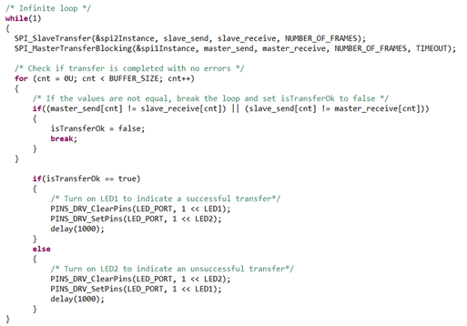
2.Source program
3.The changed program
The changed program doesn't make the SPI communication. Don't know what the problem is. Hope someone can help me. Thanks.
Hi,
this is bus signals from original demo.
You can see chip select is deasserted. Seems spi_pal driver does not allow continuous selection.
After your modification, you did it in fact, but probably it is not allowed. Bus signals is
So you need to deassert CS between each byte, you can do it as
then signals looks
and communication is correct.
You can also test dspi driver which has an option for continuous selection.
BR, Petr
Hi,
so does it mean you do not see PTD15 pin toggled by SW?
You should not set PTD15 in DSPI tab of pin_mux component, but rather in SIUL tab.
So remove it from DSPI1 and add below
generate PE code and build.
BR, Petr
Thank you for your reply.
I'm sorry we didn't make this problem clear. Let me rephrase the question.
1.Question description
The official demo program uses SPI_0 and DSPI_0 configurations in SPI communication. Where, the default pin of Chip Select output in SPI_0 is PI15.
We now need to use a different pin as the CS output pin. Here, we chose the PD15 pin in GPIO.
Generate PE code and build.
2.Source program
The source program for SPI communication is shown below.
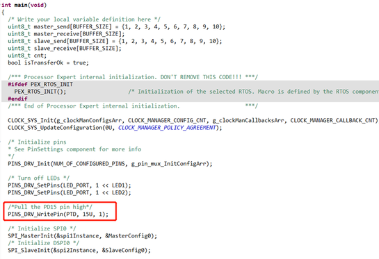
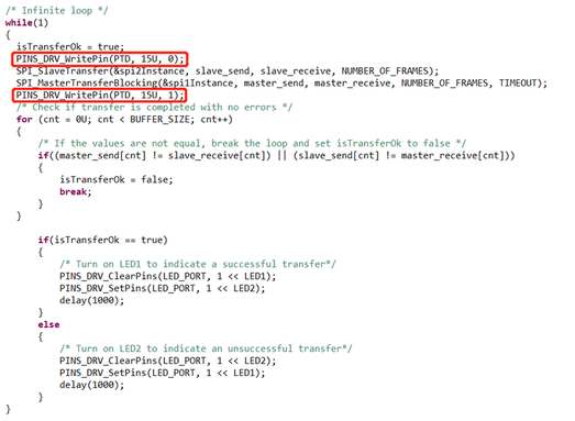
3.The changed program
First pull the PD15 pin high.
Then, pull the PD15 pin low before communication, and pull the PD15 pin high after communication.
But, the changed program doesn't make the SPI communication. Don't know what the problem is. Thank you for your help. Thanks.


