
- Forums
- Product Forums
- General Purpose MicrocontrollersGeneral Purpose Microcontrollers
- i.MX Forumsi.MX Forums
- QorIQ Processing PlatformsQorIQ Processing Platforms
- Identification and SecurityIdentification and Security
- Power ManagementPower Management
- Wireless ConnectivityWireless Connectivity
- RFID / NFCRFID / NFC
- Advanced AnalogAdvanced Analog
- Neural Processing UnitsNeural Processing Units
- MCX Microcontrollers
- S32G
- S32K
- S32V
- MPC5xxx
- Other NXP Products
- S12 / MagniV Microcontrollers
- Powertrain and Electrification Analog Drivers
- Sensors
- Vybrid Processors
- Digital Signal Controllers
- 8-bit Microcontrollers
- ColdFire/68K Microcontrollers and Processors
- PowerQUICC Processors
- OSBDM and TBDML
- S32M
- S32Z/E
-
- Solution Forums
- Software Forums
- MCUXpresso Software and ToolsMCUXpresso Software and Tools
- CodeWarriorCodeWarrior
- MQX Software SolutionsMQX Software Solutions
- Model-Based Design Toolbox (MBDT)Model-Based Design Toolbox (MBDT)
- FreeMASTER
- eIQ Machine Learning Software
- Embedded Software and Tools Clinic
- S32 SDK
- S32 Design Studio
- GUI Guider
- Zephyr Project
- Voice Technology
- Application Software Packs
- Secure Provisioning SDK (SPSDK)
- Processor Expert Software
- Generative AI & LLMs
-
- Topics
- Mobile Robotics - Drones and RoversMobile Robotics - Drones and Rovers
- NXP Training ContentNXP Training Content
- University ProgramsUniversity Programs
- Rapid IoT
- NXP Designs
- SafeAssure-Community
- OSS Security & Maintenance
- Using Our Community
-
- Cloud Lab Forums
-
- Knowledge Bases
- ARM Microcontrollers
- i.MX Processors
- Identification and Security
- Model-Based Design Toolbox (MBDT)
- QorIQ Processing Platforms
- S32 Automotive Processing Platform
- Wireless Connectivity
- CodeWarrior
- MCUXpresso Suite of Software and Tools
- MQX Software Solutions
- RFID / NFC
- Advanced Analog
- Neural Processing Units
-
- NXP Tech Blogs
- Home
- :
- 汎用マイクロコントローラ
- :
- LPCマイクロコントローラ
- :
- Re: Voltage drop every adc trigger
Voltage drop every adc trigger
- RSS フィードを購読する
- トピックを新着としてマーク
- トピックを既読としてマーク
- このトピックを現在のユーザーにフロートします
- ブックマーク
- 購読
- ミュート
- 印刷用ページ
Voltage drop every adc trigger
- 新着としてマーク
- ブックマーク
- 購読
- ミュート
- RSS フィードを購読する
- ハイライト
- 印刷
- 不適切なコンテンツを報告
Currently I am using LPC5528, I have to do 1M sample/s ADC sampling continuously, keep streaming out the value.
I attach 96M HF clock to adc with divider = 4, STS = 3, 16bit resolution.
loop cnt = 15, it will do 16 times sampling/conversion for each trigger, and write to FIFO0 and FIFO1 alternately
My implementation is,
- Init, sw trigger adc to write to FIFO0
- FIFO0 full -> adc isr
- in adc isr, sw trigger adc to write to FIFO1 and trigger DMA to copy from FIFO0 to memory
- FIFO1 full -> adc isr
- in adc isr, sw trigger adc to write to FIFO0 and trigger DMA to copy from FIFO1 to memory
- FIFO0 full -> adc isr
- repeat 3 - 6
there is a delay between each trigger, around 1us.
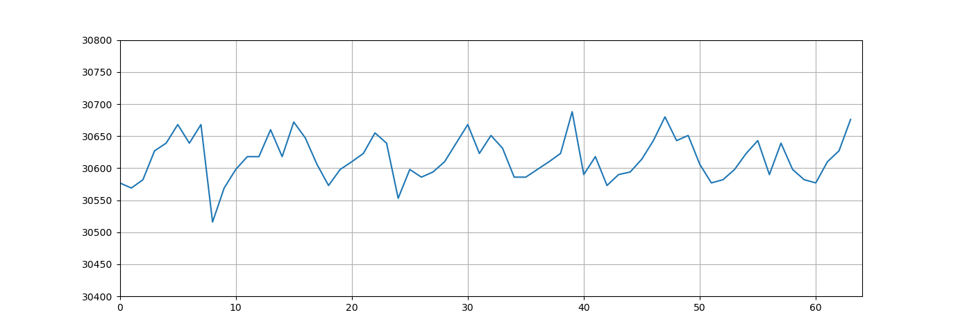
i.e. if i feed a sine wave to the adc pin, the line is not smooth at every 16 sample.
Please see Figure 1
More importantly, there is a voltage drop when the adc start, we can always see a smaller value in FIF0 1st entry.
I know the ENOB of LPC5528 16bit resolution is 12bit. But the drop is out of this range. And it happens every 16 values, so it must be related to the MCU, not a random noise.
Please see Figure 2
- 新着としてマーク
- ブックマーク
- 購読
- ミュート
- RSS フィードを購読する
- ハイライト
- 印刷
- 不適切なコンテンツを報告
Hi, Francis,
As the ADC Note3 in data sheet of LPC552x says that you can reach up to 1M Samples per second with the condition:
[3] fclk(ADC) = 24 MHz, STS = 3, Power select = 1, Average setting = 1, fs = 1 Msample/s
If I use 96MHz FRO, you have to use at least divider = 4., pls
I suppose you can set up ADC with above setting, use CTimer to trigger ADC with 1uS period and just sample one channel for each triggering. You can use polling mode to transfer ADC sample to memory, pls have a try.
BR
XiangJun Rong
- 新着としてマーク
- ブックマーク
- 購読
- ミュート
- RSS フィードを購読する
- ハイライト
- 印刷
- 不適切なコンテンツを報告
Hi Xiangjun,
I tried your suggestion. I tried two methods
CTIMER to trigger every 0.5us, and so rising edge happen very 1us, I read the adc value from RESFIFO when:
method 1. CTIMER ISR
method 2. ADC ISR (trigger completion)
Method 1: i get Zero value often, (every 2 samples, it get 1 zero) I think because sample not ready
Method 2: ADC ISR is not happened every 1us, the interval is longer than 1us.
If I increase the ADC input clock, e.g. divider = 1, then it can get sample every 1us.
What is the impact of using high ADC input clock?
Could you please provide the code that NXP use for verifying the 1MSample/s ADC?
BR,
Francis
- 新着としてマーク
- ブックマーク
- 購読
- ミュート
- RSS フィードを購読する
- ハイライト
- 印刷
- 不適切なコンテンツを報告
Hi Xiangjun,
Could NXP provide the code that used for running the test in datasheet, using fclk(ADC) = 24 MHz, STS = 3, Power select = 1, Average setting = 1, fs = 1 Msample/s ?
Besides, if I use polling mode <1us interval, it will use most of my CPU time. My application is running freertos.
If I use higher power setting, can I use 48MHz adc clock? Because LPC551X can do in this way, does LPC552X also allow this?
- 新着としてマーク
- ブックマーク
- 購読
- ミュート
- RSS フィードを購読する
- ハイライト
- 印刷
- 不適切なコンテンツを報告
Hi, Francis,
I have checked the waveform of the ADC results you attached, I think unequal sampling interval of ADC leads to the issue.
I suggest you use Timer to trigger ADC, you can set up the Timer to control the sampling interval, in this way, the equal interval can be guaranteed. I do not suggest you use software triggering mode if you require to sample in a equal interval.
Hope it can help you
BR
XiangJun Rong
- 新着としてマーク
- ブックマーク
- 購読
- ミュート
- RSS フィードを購読する
- ハイライト
- 印刷
- 不適切なコンテンツを報告
Thanks XiangJun ,
My target is stream 1MSample/s continuously. If i use timer, sample 16 time every trigger, after 16 sample finish, it will wait for next timer trigger but not start immediately. I will lose the sample in that period.
But my most important issue is the voltage drop, any idea on the voltage drop?
br,
Francis
- 新着としてマーク
- ブックマーク
- 購読
- ミュート
- RSS フィードを購読する
- ハイライト
- 印刷
- 不適切なコンテンツを報告
Hi, Francis,
Regarding the voltage drop, as you know that there is a S/H circuit, which is a capacitor actually, so in the sampling phase, the external analog source charges the capacitor, so the analog end voltage will drop because the external analog source has impedance. In order to reduce the voltage drop, you can use an analog buffer, in other words, you can use an OP amplifier, connect the inverter pin of the AMP to output pin of AMP, connect the external analog signal to the non-inverter pin, it is okay.
From software perspective, pls set the CMDHT[STS] = 0x7, but it enlarges the conversion time.
Hope it can help you
BR
XiangJun Rong
- 新着としてマーク
- ブックマーク
- 購読
- ミュート
- RSS フィードを購読する
- ハイライト
- 印刷
- 不適切なコンテンツを報告
Hi XiangJun,
I use larger STS, it really reduces the spike. However, it reduce the sampling rate a lot.
Is LPC5528 able to achieve continuously 1MSample/s sampling?
According to LPC5528 datasheet, it states ADC clock max is 24MHz.
Does it mean if I use 96MHz FRO, i have to use at least divider = 4?
If I follow the setting in datasheet, it is not 1MSample/s
fclk(ADC) = 24 MHz, STS = 3, Power select = 1, Average setting = 1, fs = 1 Msample/s
BR
Francis