
- Forums
- Product Forums
- General Purpose MicrocontrollersGeneral Purpose Microcontrollers
- i.MX Forumsi.MX Forums
- QorIQ Processing PlatformsQorIQ Processing Platforms
- Identification and SecurityIdentification and Security
- Power ManagementPower Management
- Wireless ConnectivityWireless Connectivity
- RFID / NFCRFID / NFC
- Advanced AnalogAdvanced Analog
- Neural Processing UnitsNeural Processing Units
- MCX Microcontrollers
- S32G
- S32K
- S32V
- MPC5xxx
- Other NXP Products
- S12 / MagniV Microcontrollers
- Powertrain and Electrification Analog Drivers
- Sensors
- Vybrid Processors
- Digital Signal Controllers
- 8-bit Microcontrollers
- ColdFire/68K Microcontrollers and Processors
- PowerQUICC Processors
- OSBDM and TBDML
- S32M
- S32Z/E
-
- Solution Forums
- Software Forums
- MCUXpresso Software and ToolsMCUXpresso Software and Tools
- CodeWarriorCodeWarrior
- MQX Software SolutionsMQX Software Solutions
- Model-Based Design Toolbox (MBDT)Model-Based Design Toolbox (MBDT)
- FreeMASTER
- eIQ Machine Learning Software
- Embedded Software and Tools Clinic
- S32 SDK
- S32 Design Studio
- GUI Guider
- Zephyr Project
- Voice Technology
- Application Software Packs
- Secure Provisioning SDK (SPSDK)
- Processor Expert Software
- Generative AI & LLMs
-
- Topics
- Mobile Robotics - Drones and RoversMobile Robotics - Drones and Rovers
- NXP Training ContentNXP Training Content
- University ProgramsUniversity Programs
- Rapid IoT
- NXP Designs
- SafeAssure-Community
- OSS Security & Maintenance
- Using Our Community
-
- Cloud Lab Forums
-
- Knowledge Bases
- ARM Microcontrollers
- i.MX Processors
- Identification and Security
- Model-Based Design Toolbox (MBDT)
- QorIQ Processing Platforms
- S32 Automotive Processing Platform
- Wireless Connectivity
- CodeWarrior
- MCUXpresso Suite of Software and Tools
- MQX Software Solutions
- RFID / NFC
- Advanced Analog
- Neural Processing Units
-
- NXP Tech Blogs
- Home
- :
- 汎用マイクロコントローラ
- :
- LPCマイクロコントローラ
- :
- Re: How to set up the USART Smart Card Interface on LPC435x
How to set up the USART Smart Card Interface on LPC435x
- RSS フィードを購読する
- トピックを新着としてマーク
- トピックを既読としてマーク
- このトピックを現在のユーザーにフロートします
- ブックマーク
- 購読
- ミュート
- 印刷用ページ
How to set up the USART Smart Card Interface on LPC435x
- 新着としてマーク
- ブックマーク
- 購読
- ミュート
- RSS フィードを購読する
- ハイライト
- 印刷
- 不適切なコンテンツを報告
Hello, I am trying to setup a smart card interface to communicate my mcu with a MIFARE SAM AV2 chip using the USART Smart Card Interface that is described in the user manual (12.6.2).
I am attaching the connection diagram to the post, as well as a couple captures from the user manual.
Something that's puzzling me is that the UM specifies that the TXD pin of the USART should be open drain, but upon further study the only 2 pins that are open drain in this part are being used by the i2c0 peripheral. Moreover, unlike other LPC parts, this one doesn't have a "open drain" mode for the digital pins, so that's not an option either.
My question is how exactly does one go about configuring this interface on this part? I looked for examples but found none in the support packages. I couldn't find any NXP application notes on the subject either. Is it actually supported? I know the registry to enable to mode exists, but I don't know if it is actually supported by the hardware on this particular line.
- 新着としてマーク
- ブックマーク
- 購読
- ミュート
- RSS フィードを購読する
- ハイライト
- 印刷
- 不適切なコンテンツを報告
Ok I've looking into the examples and I've gotten to the point where I get a clock out through the UCLK pin (3.7MHz) which matches my desired 9600 bauds at a 372 oversampling rate.
However, despite seeing the target device sending data through I/O line at the desired baud rate utilising a protocol analyzer, I cannot pick up this data with the USART (the interrupt never triggers).
I attempted to send data as well but I can't manage to get anything out either. I am following the example that was linked. It doesn't look like you have to do anything too fancy to get it to work, but I don't seem to get anything out. If I disable the smartcard mode it starts transmitting straight away at 9600 bauds (leaving all the other config as is) but of course this is not what I want.
I am quite confused as to what would be causing this, but I haven't really found anyone who's talked about getting this particular part to work with this interface to really have a 1 to 1 comparison or anything to go on with.
Here is a bit of the code I am using:
/* Initialize debug output via UART for board */
void smartcardInit(void)
{
uint32_t temp = 0;Chip_SCU_PinMuxSet(SC_TXD_PORT, SC_TXD_PIN, SC_TXD_FUNC_USART);
Chip_SCU_PinMuxSet(SC_UCLK_PORT, SC_UCLK_PIN, SC_UCLK_FUNC_USART);/* Enable UART clocking. UART base clock(s) must already be enabled */
Chip_Clock_EnableOpts(SC_USART_CLK, true, true, 1);/* Enable smartcard mode;
* After reset -> ISO 7816-3 compliant asynchronous smart card mode T=0 */
SC_USART->SCICTRL |= UART_SCICTRL_SCIEN;/* USARTConfig */
NVIC_DisableIRQ(SC_USART_IRQ);
// Databits, stopbits & parity
Chip_UART_ConfigData(SC_USART, UART_LCR_WLEN8 | UART_LCR_SBS_2BIT | UART_LCR_PARITY_EN | UART_LCR_PARITY_EVEN);/* Calculate clock divider for given baudrate. Round the number by (temp * 2 + 1) / 2 */
temp = ( Chip_Clock_GetRate(SC_USART_CLK) / (SC_OVERSAMPLE / 2) ) / SC_BAUDRATE_STD ; /* baud rate */
temp = (temp + 1) >> 1;Chip_UART_EnableDivisorAccess(SC_USART);
SC_USART->DLM = (uint32_t) (temp >>& 0xff;
SC_USART->DLL = (uint32_t) temp & 0xff;
SC_USART->OSR = (SC_OVERSAMPLE - 1) << 4;
Chip_UART_DisableDivisorAccess(SC_USART);/* Smartcard configuration */
SC_USART->SCICTRL &= ~((0xffUL <<| (0x3UL << 5)); /* clear guard bits and retries */
SC_USART->SCICTRL |=
(UART_SCICTRL_GUARDTIME(1)) | /* guard bits */
(UART_SCICTRL_TXRETRY(0)); /* retries */NVIC_EnableIRQ(SC_USART_IRQ);
/***************************************************************************/
Chip_UART_IntEnable(SC_USART, (UART_IER_RBRINT | UART_IER_THREINT | UART_IER_RLSINT));
Chip_UART_SetupFIFOS(SC_USART, (UART_FCR_FIFO_EN | UART_FCR_TRG_LEV0) );
/* Enable UART Transmit */
Chip_UART_TXEnable(SC_USART);
}void smartcardWrite(void){
// SC_USART->SCICTRL = 0; // if I disable the smart card mode it sends data but of course it doesn't fit what I want
uint8_t msg[16] = "abcdefghijklmnop";Chip_UART_SendByte(SC_USART, msg[0]);
Chip_UART_SendByte(SC_USART, msg[1]);
Chip_UART_SendByte(SC_USART, msg[2]);
Chip_UART_SendByte(SC_USART, msg[3]);// Chip_UART_SendBlocking(SC_USART, msg, 16);
}
I also tried doing:
/* THRE status, contain valid data */
if ( (SC_USART->LSR & (UART_LSR_THRE)) )
{
Chip_UART_SendByte(SC_USART, *msg);
}
But once you write something to the THR register LSR becomes 0 and never changes state again, indicating the data never gets through the FIFO onto the TSR to actually be sent.
I'd appreciate any help with this.
Best regards.
- 新着としてマーク
- ブックマーク
- 購読
- ミュート
- RSS フィードを購読する
- ハイライト
- 印刷
- 不適切なコンテンツを報告
Hi, Martin,
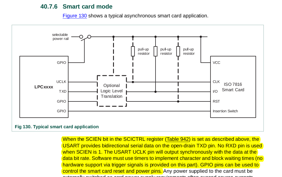
For LPC43xx, only USART0, USART2, USART3 modules support ISO7816 protocol, for detailed information about the pin connection, pls refer to section 40.7.6 Smart card mode in UM10503.pdf, I copy the part here:
In ISO7816 mode, the TX pin is an open drain and bidirectional pin.
Hope it can help you
BR
XiangJun Rong

- 新着としてマーク
- ブックマーク
- 購読
- ミュート
- RSS フィードを購読する
- ハイライト
- 印刷
- 不適切なコンテンツを報告
Yeah, I saw that part already and I attached it to the original post. In fact a large part of my post is based around asking questions about that very part of the user manual you are quoting as being the solution.
I don't think the TXD pin is actually bidirectional as it's not referenced as such in the pinout, only in that one section. The i2c pins, on the contrary, are shown as being open drain in multiple places, what makes me think this might not be the case on the USART. If you have actually used it and can verify it actually works the way you mention then that would help.
- 新着としてマーク
- ブックマーク
- 購読
- ミュート
- RSS フィードを購読する
- ハイライト
- 印刷
- 不適切なコンテンツを報告
Hi,
I think the two tickets are helpful. Pls check them.
https://community.nxp.com/t5/LPC-Microcontrollers/LPC546xx-iso7816-driver/m-p/836984
https://www.nxp.com.cn/docs/en/application-note/AN13005.pdf
BR
XiangJun Rong
- 新着としてマーク
- ブックマーク
- 購読
- ミュート
- RSS フィードを購読する
- ハイライト
- 印刷
- 不適切なコンテンツを報告
Thank you! I will give them a go.