
- Forums
- Product Forums
- General Purpose MicrocontrollersGeneral Purpose Microcontrollers
- i.MX Forumsi.MX Forums
- QorIQ Processing PlatformsQorIQ Processing Platforms
- Identification and SecurityIdentification and Security
- Power ManagementPower Management
- Wireless ConnectivityWireless Connectivity
- RFID / NFCRFID / NFC
- Advanced AnalogAdvanced Analog
- Neural Processing UnitsNeural Processing Units
- MCX Microcontrollers
- S32G
- S32K
- S32V
- MPC5xxx
- Other NXP Products
- S12 / MagniV Microcontrollers
- Powertrain and Electrification Analog Drivers
- Sensors
- Vybrid Processors
- Digital Signal Controllers
- 8-bit Microcontrollers
- ColdFire/68K Microcontrollers and Processors
- PowerQUICC Processors
- OSBDM and TBDML
- S32M
- S32Z/E
-
- Solution Forums
- Software Forums
- MCUXpresso Software and ToolsMCUXpresso Software and Tools
- CodeWarriorCodeWarrior
- MQX Software SolutionsMQX Software Solutions
- Model-Based Design Toolbox (MBDT)Model-Based Design Toolbox (MBDT)
- FreeMASTER
- eIQ Machine Learning Software
- Embedded Software and Tools Clinic
- S32 SDK
- S32 Design Studio
- GUI Guider
- Zephyr Project
- Voice Technology
- Application Software Packs
- Secure Provisioning SDK (SPSDK)
- Processor Expert Software
- Generative AI & LLMs
-
- Topics
- Mobile Robotics - Drones and RoversMobile Robotics - Drones and Rovers
- NXP Training ContentNXP Training Content
- University ProgramsUniversity Programs
- Rapid IoT
- NXP Designs
- SafeAssure-Community
- OSS Security & Maintenance
- Using Our Community
-
- Cloud Lab Forums
-
- Knowledge Bases
- ARM Microcontrollers
- i.MX Processors
- Identification and Security
- Model-Based Design Toolbox (MBDT)
- QorIQ Processing Platforms
- S32 Automotive Processing Platform
- Wireless Connectivity
- CodeWarrior
- MCUXpresso Suite of Software and Tools
- MQX Software Solutions
- RFID / NFC
- Advanced Analog
- Neural Processing Units
-
- NXP Tech Blogs
- Home
- :
- General Purpose Microcontrollers
- :
- Kinetis Microcontrollers
- :
- Re: Problems using LPTMR with 32kHz XTAL
Problems using LPTMR with 32kHz XTAL
- Subscribe to RSS Feed
- Mark Topic as New
- Mark Topic as Read
- Float this Topic for Current User
- Bookmark
- Subscribe
- Mute
- Printer Friendly Page
Problems using LPTMR with 32kHz XTAL
- Mark as New
- Bookmark
- Subscribe
- Mute
- Subscribe to RSS Feed
- Permalink
- Report Inappropriate Content
Hi all,
im trying to setup the FRDM-K22 board, to use VLPS mode running off the external 32k xtal, using the LPTMR to interupt and wake up at 8192Hz. The LPTMR IRQ will be kept less than 30us.
i have set up the ERCLK32K to be output on pin PTE0, and set the LPTMR IRQ to pulse another GPIO.
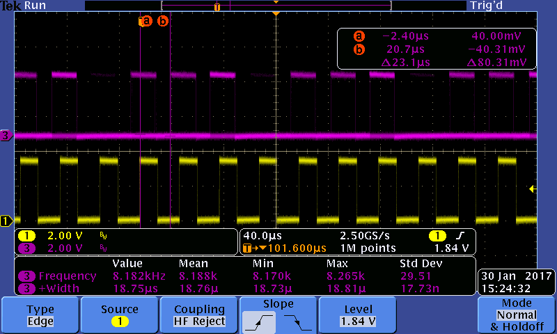
I can see them both on the scope, the gpio shows a 20us pulse, every 122us, and the clock shows 32kHz.
The current consumption is 1.22mA, which is very high, but im not sure where im going wrong?
I used BOARD_BootClockVLPR() from the example code, then use SMC_SetPowerModeVlps(SMC) in the main while loop.
I expected to see that the scope pin would go high every fourth clock period, with a small delay. But, there is a lot of jitter.
- if i trigger from the 32k clock, the gpio pin trace does not seem synced at all.
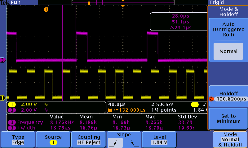
- if i increase the trigger holdoff there is a range which gets it in sync, and there is a 23us delay from the clock rising edge to the gpio pin rising edge.
- If i trigger from the gpio pin, the clock jitters a little, and there is also the 23us delay from the clock rising edge to the gpio pin rising edge.
Is the large delay to be expected? something to do with the delay in the NVIC? i tried in VLPW and VLPR and got the same 23us delay.
I cant use the debugger as it wont let me get into VLPS mode (i get a 'STOPA' error).
Can anyone give any ideas?
Thanks,
Michael.
- Mark as New
- Bookmark
- Subscribe
- Mute
- Subscribe to RSS Feed
- Permalink
- Report Inappropriate Content
Michael
The DMA is static and so won't operate when in VLPS.
The ADC can still run in VLPS when clocked from OSCERCLK (that is, an external clock source rather than the bus clock).
LPTMR can not trigger the ADC directly
Therefore I think that you will need to wake from VLPS, start an ADC conversion, wait for it to complete and then sleep again.
Or, if you have an external clock source for the ADC you can start the conversion, sleep and get the result on next LPTMR period.
If you are sampling a single ADC channel for monitoring thresholds don't forget that the ADC can be programmed with 2 thresholds to automatically monitor - if it has an external clock it will monitor these also in VLPS mode. When a threshold change is detected it's interrupt can wake from VLPS so that the state can be handled.
Regards
Mark
- Mark as New
- Bookmark
- Subscribe
- Mute
- Subscribe to RSS Feed
- Permalink
- Report Inappropriate Content
Hey mark, i had the ADC running in VLPS, by HW trigger from LPTMR. and using the ADC internal clock.
The ref manual suggests the DMA works asynchronously for some sources, and section 7.2.2 of ref manual gives more detail on DMA in stop modes. i managed to get some code working which allows VLPS mode. the chain is LPTMR_TRIG -> ADC Complete -> DMA1 (read) -> DMA0 (load next chan), then when DMA1 major loop is finished, it generates an interupt. its a bit buggy and the appnotes/manual are very hard to follow. it works well-ish, but when i use DEEPSLEEP, the DMA1 interrupt is generated at half the expected rate (twice as long). but the captured values seem correct. i think this may be me not managing sleep/irqs properly, still looking into it.
- Mark as New
- Bookmark
- Subscribe
- Mute
- Subscribe to RSS Feed
- Permalink
- Report Inappropriate Content
Michael
I made some mistakes, partly since not all K22s are the same.
- ADC can indeed be triggered by the LPTMR and I also have this in the uTasker code but was thinking triggers need to go via the PDB when scanning the manual.
- The 512k K22 has the IRC48M which can be used as internal clock to the ADC (I assume you use this) whereas the 1M K22, which I also work with, doesn't. So one needs to be careful that a K22 is not necessarily a K22....(it may have been clearer to have give some K22 chip derivatives different names because the can be very different).
- The DMA wake-up is a technique that would allow temporary DMA activity (with short exit/return in sleep mode). Again it is available on the 512k K22 (not FlexNVM one though) and not 1M K22 versions...
Regards
Mark
- Mark as New
- Bookmark
- Subscribe
- Mute
- Subscribe to RSS Feed
- Permalink
- Report Inappropriate Content
Micheal
Please specify whether you have are running the processor directly from EXTAL 32kHz (that is, switching it to MCGOUTCLK) or whether you are using it as FLL reference and then running the processor faster.
If you don't need the FLL certainly disable it since it consumes power.
Power switching from from VLPS to RUN takes up to 5.7us but this will not be valid for VLPR or VLPW to RUN (which should be without it).
Are you sure that your mode is really being set or is this just IRQ delay/jitter?
What is the power consumption that you need to achieve with this 30us IRQ every 122us?
Regards
Mark
- Mark as New
- Bookmark
- Subscribe
- Mute
- Subscribe to RSS Feed
- Permalink
- Report Inappropriate Content
Hi Mark, thanks for the reply.
I am running MCGOUTCLK from the 4MHz IRC. i checked that the FLL is disabled. i was hoping it is possible to run in BLPI with the IRC, then go to VLPS mode, waking periodically from the LPTMR. Might be that im missing something daft. Would the 5.7us wake time apply to VLPS to VLPR as well?
i had measured 12uA VLPS current earlier while getting started. now i am checking the return value of SMC_SetPowerModeVlps() (which is checking the STOPA bit). STOPA is set if running with the debugger but clear when running without it, so i think it is going to sleep.
Im not sure if im managing the power modes correctly, plus without the debugger im just setting an led based on the STOPA bit after trying to set VLPS. afaik i cant run the debugger if using VLPS. Maybe something else is waking the device after that?
I've attached the code which hopefully shows what im trying to do.
i am new to Kinetis parts and am trying to get a feel for times in and out of sleep modes / power etc, so don't have an actual power budget per se. we are considering it for a development, where it will be along the lines of 8k sampling, perhaps using the hardware accumulators / dma etc. it will probably need to be less than 300uA, but for now i'm hoping that i can manage to get the power consumption to roughly Tact/Tsleep * active current, plus some overhead.
- Mark as New
- Bookmark
- Subscribe
- Mute
- Subscribe to RSS Feed
- Permalink
- Report Inappropriate Content
Hi Michael
I have realised that your test is in fact quite an interesting case so I set up something similar in a uTasker project configuration on the same board:
#define FRDM_K22F // build for freedom board
#define RUN_FROM_LIRC // clock directly from internal 4MHz RC clock
#define FLEX_CLOCK_DIVIDE 5 // 4/5 to give 800kHz
#define FLASH_CLOCK_DIVIDE 5 // 4/5 to give 800kHz
#define BUS_CLOCK_DIVIDE 5 // 4/5 to give 800kHz
#define SUPPORT_LPTMR // enable low power timer driver
#define TICK_USES_LPTMR // use low power timer for TICK so that it continues to operate in stop based low power modes (rather than Systick)
#define LPTMR_CLOCK_EXTERNAL_32kHz // clock the low power timer from external 32kHz reference
#define LPTMR_CLOCK_RTC_32kHz // use the RTC oscillator as ERCLK32k source
#define _TICK_RESOLUTION TICK_UNIT_US(500) // 500us tick interrupt
#define SUPPORT_LOW_POWER // a low power task supervises power reduction when possible
With this configuration I get more or less your case, whereby the details are automated.
In the code I add a couple of port outputs (similar to yours) for visibility and I set the low power state that should be automatically entered on no system activity:
fnSetLowPowerMode(VLPS_MODE);
I can also set LLS if I want since the LPTR will also wake from these (I set a LLWU event on it):
INTERRUPT_SETUP interrupt_setup; // interrupt configuration parameters
interrupt_setup.int_type = WAKEUP_INTERRUPT;
interrupt_setup.int_port = PORT_MODULE; // define a wakeup interrupt on a module
interrupt_setup.int_port_bits = (MODULE_LPTMR0); // wakeup on low power timer match
interrupt_setup.int_handler = 0; // no handler since it will be serviced by the tick interrupt
fnConfigureInterrupt((void *)&interrupt_setup); // configure interrupt
The first things to note are:
1. I set 800kHz flash clock since if you want to use VLPR and VLPW this is the maximum that it can have. You didn't state what Flash/Bus clock rate you have.
2. The second thing to consider is the basic interrupt latency involved. This is 12 cycles for the Cortex M4, but with FPU it increases to 29 (unless lazy stacking is used). I am assuming our K22 with FPU is taking 29 cycles (in fact it may be best to use a non-FPU in some cases!). 29 cycle at 4MHz are 7.25us. There are a few additional cycles needed to save registers in the interrupt handler and to read the interrupt vector and to set the outputs, so let's say 35 (8.75us). The interrupt vector may be taken from Flash and instructions are probably in flash and there may be some extra delay on actually loading these (800kHz) depending on cache state.
When I didn't use the VLPS (always run) I measure about 9.5us (+3us/0us jitter), which is fairly close to the expected value.
When I use VLPS mode between operations I measure 12.0us with about +/- 0.1us jitter.
What I see is that there is a delay of 1.7us between the LPTMR rising edge and the completion of the first instruction in code (I set an output for visibility).
Since my results don't show the >20us delays that you have I suggest that you need to revisit the tests to check the basics (maybe without low power switching to verify the interrupt basics).
The other questions that I would also ask is whether a KL series device may in fact be more suitable for your application? They are more streamlines for low power and if you use a slow clock there is not much point in the fast K22 (nor its FPU).
These are my analyser shot as comparison:

The top is of course the 32kHz clock.
The falling edge on the lower trace is the IRQ that the LPTMR triggers (and the delay from the clock's rising edge to it is 12us). This low pulse is the uTasker OS TICK handler, which will schedule a task (that runs at every tick).
The middle trace shows the instruction just after moving back from VLPS to RUN (immediate rising edge) - it then enables interrupts so that the interrupt that woke from the VLPS mode can actually fire (the VLPS state needs to be entered with disabled interrupts to avoid risk of system failure!!).
The middle trace toggles (low) again in the task that is scheduled.
It is interesting to note that the delay from the LPTMR wakeup and the task being scheduled is also very exact/consistent due to the fact that there is no randomness (the wake up always continues from the exact same code location after the IRQ). The OS will set the low power state after the task has run, it has verified that nothing else needs to be executed and it is safe to sleep again - the middle trace goes high again when the next VLPS state is commanded.
The reason why I set 500us period (and not 122us) is because the complete cycle is around 170us due to the OS operation and if I set it lower it will not be able to sleep since the next LPTMS Tick already arrives before it can. The ratio of VLPS and RUN is then also not of interest because it will be in RUN mode too much of the time (percentage).
This raises another interesting question which is also a frequent subject in low power designs. You have set a very slow processor clock and it is causes the OS operation (since it has too many timers, queues, tasks to be checked in my configuration) to take either too long or a high percentage of the cycle period. The result is a high percentage in RUN and only a small benefit from the VLPS (or other) mode. This can be quite inefficient.
The other strategy is to sleep deep for as long as possible, then run "as fast as possible" (to keep RUN time short) to get back to sleep as soon as possible. Then there is a high percentage of low power in the cycle - a high short current peak but an average consumption which is still very low.
Which ever chip you finally go for you may find it useful to consider which strategy is actually best based on the specific application and its cycle requirements. The advantage of the uTasker project is that I can run the exact same method on any Kinetsi (K, KL, etc.) without any changes (apart for the board define and clock speeds) so I can just chose the type that is finally used whenever it has been identified.
Probably in this design I would not have any tasks and do the IRQ handling directly in the interrupt.
Alternatively it is in fact not even necessary to have an interrupt (in the cycling case and single wake up source) since the handling code can immediately be executed after the sleep instruction, thus even saving interrupt latency!
Tell me how you get on and if you see anything else worth investigating further.
Regards
Mark
- Mark as New
- Bookmark
- Subscribe
- Mute
- Subscribe to RSS Feed
- Permalink
- Report Inappropriate Content
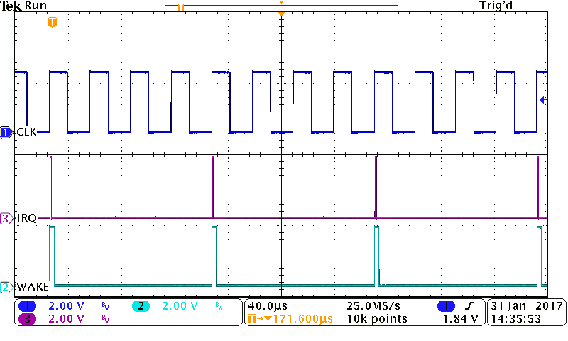
Thanks for helping out on this. Its really helpful. Disabling interrupts before vlps rings a bell, why is this? I've added it in, and added another gpio for the main loop 'WAKE' which goes high immediately after _WFI(), and low immediately before.
attached image - this time the led is showing yellow so i knew it was switching quickly between red and green. i can see that as you suggested things are taking too long.
the third 'IRQ pulse' comes early because it has not went back to sleep or disabled interupts yet. the LED shows that STOPA is set just before this.
I had set the Flash to 1MHz which i gues isnt helping if it needs to be <800KHz. maybe this is what is holding it up so much?
i will try to rework things to use the FLL at higher frequency. I'm aware of the low power schemes your suggesting and am planning on doing this.

- Mark as New
- Bookmark
- Subscribe
- Mute
- Subscribe to RSS Feed
- Permalink
- Report Inappropriate Content
Micheal
If you are not using module wake-up you can't be in LLS mode in fact because otherwise you wouldn't be able to wake out of them with the basic LPTMR IRQ. My 25us delay out of LLS did make me think that it was what you were seeing but it seems not.
You should get no debugger dependency (I tested with debugger connected and without). Make sure there is no semi-hosting or such enabled so that the debugger is active in some way. Basically never perform critical investigations with debuggers to ensure they don't influence, if in doubt - the case without debugger is the one that will exist in the future.
You need to enter low power state with interrupt disabled to avoid a race state possibility where the wake-up fires as the instruction is in the pipe-line. If it does this the interrupt will be serviced 'before' sleeping and there is a risk of never waking up (if the interrupt is not cyclic) or after a delay where the code thinks it is handing the first wake up when it is in fact already the second..... The Cortex wake-up is very clever because it is the "masked pending" interrupt that wakes and not the interrupt itself that triggers it, which makes this safe (I worked with STR91xx chips from ST Micro in the past where they did this wrong and wake-up was not usable due to this risk - they wrote that one needed to sleep with interrupts enabled to ensure that the wake-up worked and that one should only move to sleep when no interrupt "can arrive" during the process - of course impossible to guarantee and so totally unusable...).
I would also always power cycle the board before testing since some low power bits are sticky and mode changes may not always works as expected unless the framework is really handling everything correctly.
Beware that the low power modes will stop a lot of clocks and things like DMA will not operate while sleeping. You need to do work quickly when running at full speed and do effectively "nothing" when not - most peripherals will be frozen and so not functional! Read the peripheral and clock lists in the various states carefully to avoid planning something that will not be feasible. You will also need to ensure that any peripheral operations in progress are really "completed" before transitioning otherwise the operations will tend to fail.
Flash > 800kHz is only a restriction for VLPR and VLPW modes where it is an illegal speed.
At present I still don't understand the results that you are seeing since you should be able to get pretty fast exit from VLPS (<2us). If I switch to bypass the OS once everything is cycling I can get out of VLPS and back in again in a few us by using the IRQ purely as wake-up trigger and not needing to service it. If you tell me the name of the pins that you have connected for measuring I can send you a binary for comparison (to exclude a HW difference).
Note that I am working on a series of short videos where I already have some concerning low power modes
https://www.youtube.com/watch?v=kWNlsAoMly4&list=PLWKlVb_MqDQFZAulrUywU30v869JBYi9Q
The uTasker low power automations have been used intensively in products for a couple of years (eg. with 6 UARTs that need to be handled dynamically without any risk of data, but micro-amper current draw when no activity, which VLPS is perfect for) whereby I found the original NXP examples to be useful for only basic tests since they were not expecting more than one certain thing to be able to happen at any time.
Regards
Mark
- Mark as New
- Bookmark
- Subscribe
- Mute
- Subscribe to RSS Feed
- Permalink
- Report Inappropriate Content
Michael
As reference to what is achievable in VLPS and LLS when I move to low power cycle mode (that is I allow the low power loop to bypass the OS) I have the following recordings. I can switch between automatic mode and the OS bypassed mode as I want (eg. if I have a UART based command line exists I can run in the optimised loop to save most power but if I detect a UART interrupt pending I can temporarily switch to the full OS operation to handle the interaction with the user before returning to the optimised loop mode again.
In both cases I have the wake-up taking place on a LPTMR match, a virtual interrupt handler executing (I write "virtual" because the wake up was due to a pending interrupt and I never enable interrupt or have the interrupt latency involved).
Then it shows this cycle followed by a cycle which quits the loop to schedule tasks and such (which then needs to take the interrupt vector).
VLPS (close up)
1. LPTMR edge to processor executing instructions = 2us
2. Virtual interrupt handling taking place (bottom trace) 6us later
3. I have a short routine that just clears interrupts and does a counting function to set the mode back after a while takes 16us (shown further below)
4. VLPS mode entered again 3us after the handling is complete.

Therefore no interrupt latency and the RUN time is kept as short as possible
VLPS (low power cycle followed by 'normal' OS mode after the next wakeup)

The main observation is the interrupt latency and of course the OS overhead to schedule tasks and return back to the VLPS state (with its advantages at complete system level but as a trade off in that period). The recording in this section has been discussed in detail in previous posts.
LLS (closeup)

The wake-up time from LLS to RUN is much longer (25us as opposed to 2us) but the rest is the same as in the previous case since there is no interrupt latency issues (see next for comparison).
LLS(low power cycle followed by 'normal' OS mode after the next wakeup)

The delay between wakeup event and the start of handling it increases from 30us to 96us due to the interrupt latency (in second cycle).
This gives quite a good insight into the advantage of being able to control the RUN handling in such a cycle without needing to handle interrupts. It reduces the ratio of RUN to VLPS or LLS importantly and so can allow overall current to be reduced quite significantly (due to removal of interrupt latency overhead, especially after LLS wakeup!).
I can now control this in the uTasker project with the define
LOW_POWER_CYCLING_MODE
The call-back function that needs to be supplied is rather "low level" since it is up to the user to also ensure that wake up sources are cleared (this needs to be done also in the NVIC manually since the interrupt is not taken as normal). However this is all that is needed for a complete 'optimised' low power cycle based framework, also with the capability to switch between full scheduling or looping operation as one desires.
Once I have a video showing a complete system operating using this technique I'll give a link - where I will also show a little more details concerning the overall operation.
extern int fnVirtualWakeupInterruptHandler(int iDeepSleep)
{
if (iLowPowerLoopMode == 0) { // if not in low power loop mode ignore
return 0;
}
if (iDeepSleep == 0) { // loop only in deep sleep modes (not wait based)
return 0;
}
TOGGLE_TEST_OUTPUT(); // toggle output for measurement
LPTMR0_CSR = LPTMR0_CSR; // clear pending interrupt at LPTMR (wakeup source)
fnClearPending(irq_LPT_ID);
*(volatile unsigned char *)(LLWU_FLAG_ADDRESS + 2) = MODULE_LPTMR0;
// reset the wakeup flag (write '1' to clear) needed only from LLS
fnClearPending(irq_LL_wakeup_ID);
// Insert application specific code here....
//
iLowPowerLoopMode--; // go back to scheduler control after a number of cycles
TOGGLE_TEST_OUTPUT(); // toggle output for measurement
return 1; // stay in loop
}
Regards
Mark
- Mark as New
- Bookmark
- Subscribe
- Mute
- Subscribe to RSS Feed
- Permalink
- Report Inappropriate Content
Hi
I have attempted to explain the basic concept and show the power saving due to bypassing the wake-up interrupt latency here:
https://youtu.be/v4UnfcDiaE4
Regards
Mark
- Mark as New
- Bookmark
- Subscribe
- Mute
- Subscribe to RSS Feed
- Permalink
- Report Inappropriate Content
Hi Mark,
i had a look, really good explanation, cheers. i was going down a similar road as well, but was in the process of trying it out when i bricked the devkit!! second one now. ive seen some of your other posts and elsewhere on the net, looks like somehow i may have secured the flash :smileysad: got another kit coming today, but i'm looking into how that happened at the moment.
From earlier:
At present I still don't understand the results that you are seeing since you should be able to get pretty fast exit from VLPS (<2us). If I switch to bypass the OS once everything is cycling I can get out of VLPS and back in again in a few us by using the IRQ purely as wake-up trigger and not needing to service it. If you tell me the name of the pins that you have connected for measuring I can send you a binary for comparison (to exclude a HW difference).
same here, i was getting somewhere before the board stopped working. Im using the FRDM-K22, with PTD2 as SCOPE1 and PTB16 as SCOPE2, and PTE0 as 32k clock out.
--
the issue i see is that if the 250us wake up time is when you know you have to do a task, like some 4kHz process, then you will always have to use the context switch anyway? or if not you could handle it in the main thread, but it would still be taking a time longer than the 60us ish, so you would end up back with not sleeping for very long?
also, the main current was taking 3.5mA and the low power mode reduced it to 1.5mA. is there other things going on in utasker here, or do you know why it didnt drop to 0.8-0.9mA, if it managing to sleep for 75-80%?
- Mark as New
- Bookmark
- Subscribe
- Mute
- Subscribe to RSS Feed
- Permalink
- Report Inappropriate Content
Michael
If flash is secured it can be unlocked with KDS (it will tell you that it is secured and ask where you want it to un-secure it).
I have a couple of boards that stopped communicating (always the OpenSDA - as if it were dead).
In one case, while doing low power tests I found that I always corrupt the OpenSDA loader if I leave the current measurement jumper unconnected and connect to a Win 10 PC. This can be explained by the fact that (at least on that board) not having the target processor powered causes the OpenSDA chip (K20) to start in its own bootloader mode, which is not compatible with Win 10. Win 10 tries to write hidden files to its USB-MSD device and corrupts the loader. I can recover from this be reloading the OpenSDA loader on a Win 7 PC - I am very careful to not let this happen when doing current measurements but sometimes it still does....
To the issues:
- Basically if the system (however performed and whether in interrupts, main loop, tasks or in the "virtual Interrupt Handler") need 249us of every 250us cycle to do its work the maximum saving is 1/250% in terms of power reduction, even if there were zero overhead. The hard limit at the end of the day is therefore what the handler is doing - any additional overhead to control the handler (wake-up/sleep times, interrupt latency, task switching, other code in the system) is on top of this and so is best kept to a minimum.
- If I use the "LOW_POWER_CYCLING_ENABLED" state I have absolute maximum performance since there is neither interrupt latency, nor scheduling overhead. If I don't need or want the system to be responsive to other events I don't need to ever leave this state and so I can stay therefore.
- However I have the advantage that I can power up the system with the full operation (eg. allowing a user to configure the system in a comfortable manner if that is what the product also requires to be able to do). At some point I can switch to the optimal cycling mode with close to zero overhead.
- The further advantage is that I can temporarily switch to the full-operation (eg. at a defined time).
- If I want, as in the reference, I can still allow events - such as the command line console - to briefly go back to the full operation (with its higher power consumption) to handle the input. Of course if I don't want this I simply don't allow it.
Therefore there is no compromise if I want "pure" low power cycle operation. But in many real world designs one will still like to have other capabilities, even if only used once during the very first setup; after that it still has zero effect on the final operation and its efficiency.
To the currents:
There are unfortunately still some surprises which I can't (yet) fully explain. In the reference case the only activity outside the low power cycle loop is a RTC interrupt every 1s (negligable) plus the command line handling. The command line handling "only" takes place when used so if I don't touch the terminal it adds no overhead - if I do touch it the system requires more power for maybe one or two cycles - depending on what it needs to do. It doesn't affect the cycle operations though since this is still taking place in an interrupt and so no cycles are lost - it is only the temporary power consumption that is affected.
Therefore uTasker itself is not involved during the tests; no further activity whatsoever.
These are some things that I have noted concerning actual current consumption:
1. If I turn on my board (in WAIT mode, which means that the processor is set to the WAIT state with no activity (i.e. the 50% or so with the 25us cycle)) I measure 2.5mA. The current slowly increases up to about 3.5mA - possibly as the chip heats up (?). I didn't notice this effect in such tests before....and I have been doing them regularly on many different Kinetis parts for some years, whereby my typical TICK is 50ms (and not 250us).
2. If I test with 250us cycle time I really don't see the linear saving. It is as though there is an invisible period where the processor still consumes power - it doesn't follow the rule that you and I both expect that if the duration in each cycle is halved the current should halve. In fact there is very little difference in the current consumption between 50% and 100% duty cycle. It improves only when the duty cycle gets below about 40% or so.
I was in two minds as to whether it would be best to show a 250us or 500us cycle period. The results are NOT the same - it is as if this invisible "dead-time" is much less of a factor and the relationship is closer to that expected when the cycle period is increased.
Here is a complete set of measurements using 500us and 250us cycle so that you can see (4MHz core and 800kHz Flash so that VLPR is possible). There is some limit that can't be explained by the pure relation between being in RUN and being in VLPS (or other) since the waveforms measured show that the processor is RUNning for the same time in each case.
500us cycle period
RUN 4.2mA
WAIT 3.5mA (lpc has no used)
STOP 2.2mA (with lpc = 1.1mA)
VLPR 2.45mA (lpc has no effect)
VLPW 1.47mA (lpc has no effect)
VLPS 2.2mA (with lpc = 0.9mA)
LLS2 2.7mA (with lpc = 0.8mA)
This all makes pretty good sense - note that the low power loop mode is even more effective in LLS2 because we know that it save much higher interrupt latency (for previous investigations) so the theory and practice are doing quite well...
250us cycle period
RUN 4.2mA
WAIT 3.8mA (lpc has no used)
STOP 3.8mA (with lpc = 1.8mA)
VLPR 2.45mA (lpc has no effect)
VLPW 2.3mA (lpc has no effect)
VLPS 3.75mA (with lpc = 1.6mA)
LLS2 3.9mA (with lpc = 1.7mA)
I monitor the waveform in each case and the waveforms are as expected but one can see that the current is not. There are three interesting cases:
1. STOP mode is not effective at saving current in the 250us case, although the STOP mode is really entered for 50% of the time...!
2. VLPS is the same (makes sense because both are based on the STOP mode)
3. LLS mode is only effective when using the "low power cycle" mode due to the fact that its wake-up time is rather long and it can't quite achieve the rate - effectively it results in it always being in RUN mode since it has to wake up as soon as it gets there....With the LPC optimisation it can benefit from some decent sleep time....
My first suspicion is that there is some "energy" requirement to move to and from the STOP based modes that causes a "knee" in the current measurements and so a limit. Current saving only becomes effective when the STOP/RUN ratio is lower than around 35%. If this is not achieved it is basically useless...(at least in this configuration)
The overall conclusion is that one needs to TEST, TEST and TEST - also in the REAL conditions that the final product will be required to run under.
But I went a little further and checked what would happen if we allow the processor to run faster when it is not in a sleep state - setting the 48MHz IRC as clock to give 48MHz core and 24MHz Flash.
250us cycle period
RUN 17.0mA
WAIT 15.3mA (lpc has no used)
STOP 2.22mA (with lpc = 1.2mA)
VLPR - not possible
VLPW - not possible
VLPS 1.95mA (with lpc = 0.86mA)
LLS2 2.44mA (with lpc = 0.77mA)
As I have noted on several occasions - sometime sit is better to RUN fast and Sleep deep for as long as possible. These results show that the practice again follow the theory - this suggests more strongly that switching in and out of STOP mode with a slow clock is energy intensive because now we are running at a good speed when active and still achieving less current overall.
Now I also have no problems running as your preferred 122us cycle since even occasional scheduling overhead is peanuts overall in terms of actual overhead.
122us cycle period
RUN 16.8mA
WAIT 16.1mA (lpc has no used)
STOP 2.92mA (with lpc = 1.81mA)
VLPR - not possible
VLPW - not possible
VLPS 3.70mA (with lpc = 1.58mA)
LLS2 4.66mA (with lpc = 1.54mA)
I would probable choose VLPS with lpc at this faster working rate because I would also allow use USB optionally. These are the recordings at 122us for VLPS (without lpc) and (with lpc)

RUN/SLEEP ratio 12.58us/122us

RUN/SLEEP ratio 3.42us/122us
LPT saving 9.16us per 122us period, which equates to (real) 57% saving in power consumption.
Don't forget that I still have a complete system (the serial command shell reacts identically and if I want to use USB for a short period where the current consumption doesn't have priority I can so with without any effort). Therefore there is no advantage (only disadvantages in fiddly development/tests and potentially much higher costs and maintenance later when features need to be added) of not using the scheduler.
Regards
Mark
P.S. Would you like me to post binaries for you to test and verify your HW? Unfortunately I had to stop the 32kHz clock output because it shared the UART Tx line, so I need to disable the serial interface if the clock reference needs to be measured. Since the clock/wake-up delays (at least at 4MHz) are known I decided to not use it any more and just rely on the SLEEP/RUN ratios because the command line is extremely useful for doing efficient tests.
Alternatively, the uTasker development (including all this on the development branch) is available as GIT and SVN repository for uTasker users. If you want a free commercial license to avoid needing to rely on the NXP code (which is not designed for dynamic use) just tell me. I still support free users here - especially ones who are obviously clued up since it helps drive the development (which is already leaps and bounds beyond the NXP packages, but gets more ahead each day ;-)
- Mark as New
- Bookmark
- Subscribe
- Mute
- Subscribe to RSS Feed
- Permalink
- Report Inappropriate Content
hi mark thanks again. sorry for the late reply. I've been trying to get my head around the adc->dma to see how i can avoid waking up as much. still digging but not sure if its going to give an advantage in VLPS mode. do you know if using the IRC48M clock when waking from VLPS - can this somehow be used to drive the DMA?
(eg. use the LPTMR to trigger the ADC in VLPS mode, with the DMA taking care of reading result and setting up the channels)?
I'm ok for the binaries for now thanks, im getting on with this for now.
cheers,
Michael.
- Mark as New
- Bookmark
- Subscribe
- Mute
- Subscribe to RSS Feed
- Permalink
- Report Inappropriate Content
Michael
I have performed some tests in LLS3 and have some interesting findings.
There is now a delay similar to the one that you measured.
Also note that in VLPS mode there is no problem with the debugger - only in LLS is it no longer possible to work with it.
These make me believe that you are somehow confusing LLS with VLPS.
The LLS wake up is however not as expected! This is what it now looks like:

The first marker is the edge which I believe wakes the processor from LLS mode. Now it takes 25.2us for the first instruction to be executed after waking, which is a lot longer than the max. 6us quoted in the data sheet; although the value in the data sheet if for 80MHz which suggests that our 4MHz clock is slowing recovery!
The next very surprising fact is that the wake up interrupt that caused the LLS to RUN recovery has a latency of 56us!!!!!!. I proved that the processor is executing instructions at the normal speed before taking the interrupt but it is much slower than when an interrupt is (normally) taken (typically around 8us with FPU state saving).
The second trace going high signals that the wakeup interrupt (due to LPTMR wakeup module) has been reached. This calls the OS tick handler (since the LPTMR interrupt is also pending anyway) and clears the sources - the bottom trace shows the actual tick handler being called from the LLWU interrupt.
Although not as extreme as when the interrupt is taken, returning from the LLWU interrupt also takes about twice as long as normal. This makes me wonder whether this exception is special in some way and is having to save and recover more information that other interrupts (?). In any case it looks to be similar to the approx. 23us that you have been puzzling over. In fact from the rising edge of CLKOUT32k to the IRQ I get about 82us, which means that you may be measuring from the wrong edge - the trigger was in fact 2 clock cycles before the one that you start measuring from !
The second trace flips bits for a while (I used this to prove that the interrupt is taken immediately and any slowness is not due to the interrupt being delayed - the bit flipping speed is the expected instruction speed). The rest is then as before.
Therefore I can show the operations in and out of VLPS and LLS3 to be basically equivalent in terms of the behavior flow but LLS3 recovery is taking unexpectedly long!
In fact, the LLS3 saving of current (about factor 3 over VLPS) is deteriorated due to the longer time that it takes to do the work in this sort of environment (quickly repeated cycle where the percentage of time in RUN should be kept as low as possible).
My feeling is therefore that VLPS is the one to go with (when the % of the period is fairly high. I would also look at running as fast as possible when in RUN to keep the time short. This may also help LLS performance since the LLWU interrupt latency should also be much better (it is presently dead-time which is consuming RUN mode current but does very little useful work that is visible and of any importance to the application). Also I would seriously consider a part without FPU to keep latency as low as possible.
If you have only one interrupt that does the cyclic work no interrupt is needed (as explained in previous post) and thus interrupt latency can be removed altogether.
Regards
Mark
- Mark as New
- Bookmark
- Subscribe
- Mute
- Subscribe to RSS Feed
- Permalink
- Report Inappropriate Content
These make me believe that you are somehow confusing LLS with VLPS.
Ive never set anything for LLS mode, and haven't seen it in the SMC registers at any point so i'm not sure how, but i will look into it.
Also, i tried new code, stripped down. I tried without VLPS, ie i booted to normal run mode. then:
while (1)
{
/* Tmr setup for IRQ, so can go to sleep here */
APP_goToSleep();
if( schedule_1_flag )
{
currentCounter = lptmrCounter;
schedule_1_flag = false;
//PRINTF("\r\nirq#%d \r\n", currentCounter); ;
}
//APP_setLedColour(debugLedColour);
}
inline void APP_goToSleep(void)
{
SCB->SCR |= SCB_SCR_SLEEPDEEP_Msk;
__disable_interrupt();
//SMC->PMCTRL &= ~SMC_PMCTRL_STOPM_MASK; //temp - 0 is normal stop
// SMC->PMCTRL &= ~SMC_PMCTRL_STOPM_MASK;
// SMC->PMCTRL |= (2U); //temp - short as poss
/* Go To Sleep */
GPIOB->PCOR = 0x00010000; //PTB16 temp - short as poss./* read back to make sure the configuration valid before enter stop mode */
(void)SMC->PMCTRL; //arm doesnt wait for previous line before wfi...
__WFI();
/* Wake Up */
GPIOB->PSOR = 0x00010000; //PTB16 temp - short as poss.
__enable_interrupt();
/* check whether the power mode enter VLPS mode succeed */
if (SMC->PMCTRL & SMC_PMCTRL_STOPA_MASK)
{
//debugLedColour = kLED_RED;
APP_debugLED_RED();
}
else
{
//debugLedColour = kLED_GREEN;
APP_debugLED_GREEN();
}
}
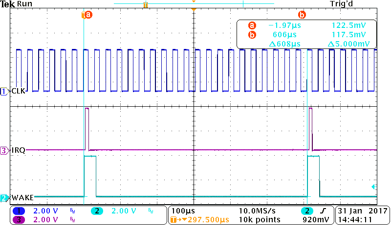
its really weird, it is a lot cleaner, but:
with the debugger - the irq works every 4th clock as expected,
without the debugger it now triggers every 20th clock!?
I have attached pictures to explain.
I then when back to VLPS and the irq is every 4th cycle with or without debugger, but has the previous problem ("yellow STOPA LED").
My feeling is therefore that VLPS is the one to go with (when the % of the period is fairly high. I would also look at running as fast as possible when in RUN to keep the time short. This may also help LLS performance since the LLWU interrupt latency should also be much better (it is presently dead-time which is consuming RUN mode current but does very little useful work that is visible and of any importance to the application). Also I would seriously consider a part without FPU to keep latency as low as possible.
yep thanks, makes sense. i am going to try to use VLPS/STOP mode, and wake to RUN mode, using the FLL. and will compare. a particular mode of our device will be to sample a number of ADC channels at 8kHz, but filter and decimate down to probably 512 or 256. so im actually wanting to see if the LPTMR drive this, and use the DMA. i was going to look at the lptmr hardware trigger / adc accumulator / dma etc later to allow waking up less, but at the moment im still finding my way around these power / clock modes!