
- Forums
- Product Forums
- General Purpose MicrocontrollersGeneral Purpose Microcontrollers
- i.MX Forumsi.MX Forums
- QorIQ Processing PlatformsQorIQ Processing Platforms
- Identification and SecurityIdentification and Security
- Power ManagementPower Management
- Wireless ConnectivityWireless Connectivity
- RFID / NFCRFID / NFC
- Advanced AnalogAdvanced Analog
- Neural Processing UnitsNeural Processing Units
- MCX Microcontrollers
- S32G
- S32K
- S32V
- MPC5xxx
- Other NXP Products
- S12 / MagniV Microcontrollers
- Powertrain and Electrification Analog Drivers
- Sensors
- Vybrid Processors
- Digital Signal Controllers
- 8-bit Microcontrollers
- ColdFire/68K Microcontrollers and Processors
- PowerQUICC Processors
- OSBDM and TBDML
- S32M
- S32Z/E
-
- Solution Forums
- Software Forums
- MCUXpresso Software and ToolsMCUXpresso Software and Tools
- CodeWarriorCodeWarrior
- MQX Software SolutionsMQX Software Solutions
- Model-Based Design Toolbox (MBDT)Model-Based Design Toolbox (MBDT)
- FreeMASTER
- eIQ Machine Learning Software
- Embedded Software and Tools Clinic
- S32 SDK
- S32 Design Studio
- GUI Guider
- Zephyr Project
- Voice Technology
- Application Software Packs
- Secure Provisioning SDK (SPSDK)
- Processor Expert Software
- Generative AI & LLMs
-
- Topics
- Mobile Robotics - Drones and RoversMobile Robotics - Drones and Rovers
- NXP Training ContentNXP Training Content
- University ProgramsUniversity Programs
- Rapid IoT
- NXP Designs
- SafeAssure-Community
- OSS Security & Maintenance
- Using Our Community
-
- Cloud Lab Forums
-
- Knowledge Bases
- ARM Microcontrollers
- i.MX Processors
- Identification and Security
- Model-Based Design Toolbox (MBDT)
- QorIQ Processing Platforms
- S32 Automotive Processing Platform
- Wireless Connectivity
- CodeWarrior
- MCUXpresso Suite of Software and Tools
- MQX Software Solutions
- RFID / NFC
- Advanced Analog
- Neural Processing Units
-
- NXP Tech Blogs
- Home
- :
- General Purpose Microcontrollers
- :
- Kinetis Microcontrollers
- :
- Re: Problem with Kinetis KL02
Problem with Kinetis KL02
- Subscribe to RSS Feed
- Mark Topic as New
- Mark Topic as Read
- Float this Topic for Current User
- Bookmark
- Subscribe
- Mute
- Printer Friendly Page
- Mark as New
- Bookmark
- Subscribe
- Mute
- Subscribe to RSS Feed
- Permalink
- Report Inappropriate Content
Hi all,
I have a peculiar problem with a kinetis I hope the community can help me with. The problem is similar to a design based upon a coldfire controller (https://community.freescale.com/thread/365050) but have subsequently decided to switch to the kinetis. For the coldfire I used a P&E Multilink Interface and for the kinetis a Mulitlink Universal (brand new).
The pcb layout for the kinetis is for a specific design problem but for now I've only populated the pcb with the essentials to test the MCU. The MCU is a MKL02Z32VFG4 (a 16 pin QFN package). The MCU has power and ground connected to it with a decoupling cap in between. The same power supply is used to power the Multilink Universal. It is a 3.3V stable bench supply. The Multilink is connected to the SWD_CLK, Reset and SWD_DIO of the MCU. A 8.6kohm resistor is used as pull-up for the reset (also had a capacitor from reset to ground but it did not make a difference).
Procedure:
1) I wrote a simple program to toggle one of the pins (PTB1) (in CodeWarrior 10.4).
2) I programmed the MCU. Initially it did not want to program but reducing the debug shift frequency to 0.04MHz did the trick.
3) I then remove the debug interface, power cycle and let it run.
Results:
1) The MCU runs happily for a while but then starts to fail (can be from seconds to hours).
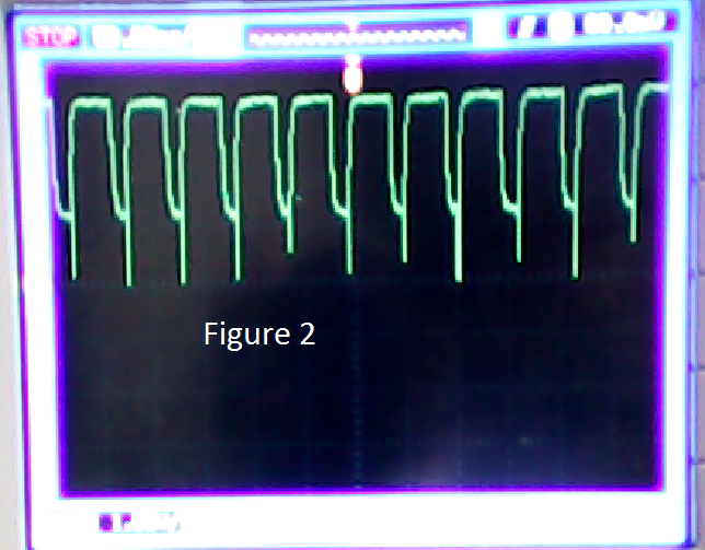
2) I can get an indication on when it starts to fail by monitoring the reset pin. Initially the reset pin is stable but then a square wave starts to appear (see figure 1). This however progress to become more unstable until as shown in figure 2.
3) Can not reprogram the MCU when when reconnected to programmer (in fact some of the MCUs start to smoke and are damaged permanently!!).
The above was tried on different PCBs with different designs and different power supplies, with more or less the same results.
Questions:
When the MCU is flashed, is a crc done? Could the strange behaviour be as a result of the MCU being flashed incorrectly?
Help will greatly be appreciated!
Regards
Philip
Solved! Go to Solution.
- Mark as New
- Bookmark
- Subscribe
- Mute
- Subscribe to RSS Feed
- Permalink
- Report Inappropriate Content
Hi all,
It appeared the solder flux expired and caused all the issues!
Regards
Philip
- Mark as New
- Bookmark
- Subscribe
- Mute
- Subscribe to RSS Feed
- Permalink
- Report Inappropriate Content
Hi all,
It appeared the solder flux expired and caused all the issues!
Regards
Philip
- Mark as New
- Bookmark
- Subscribe
- Mute
- Subscribe to RSS Feed
- Permalink
- Report Inappropriate Content
Me again. I tried to help you with the Coldfire problem.
> I programmed the MCU. Initially it did not want to program but reducing the debug shift frequency to 0.04MHz did the trick.
Is that a problem? I've never looked at these chips (but have just downloaded the Data Sheet and Reference Manual). What internal clock rate do they default to?
Anyway, not the current problem...
You've had ColdFire chips dying and now the Kinetis ones are. There are two common factors. You're the first one. The other possibility is your bench supply. I have a bench supply in a cupboard here, built by an idiot who really didn't know what he was doing. Meaning me, when I was about 20. It has a nasty fault. When I turn it on or off, one of the supplies when set to 5V glitches to about 20V. Make sure your one isn't doing anything nasty like that.
> (see figure 1).
You can insert pictures in-line in this forum if you want to make your posts easier to read.
> some of the MCUs start to smoke and are damaged permanently
That's called "letting the magic smoke out", or "failing the smoke test". That's really bad. Software can't do that (since the HCF instruction on the 6800).
Don't you have an oscilloscope you can take a DIGITAL capture of? Those photographs only show me that the timebase is set to 50 ms/div because you wrote that on top of the picture. Otherwise they're out of focus, badly overexposed and don't show the voltage/division or where the zero line is. I would like to know the voltage levels of all parts of the waveform. For instance, is that spike in Figure 2 going below zero? If it is showing that, is it "real" or is the oscilloscope probe connected badly? If any pins on the chip ever go below -0.3V or above VDD+0.3 you can kill the chip.
You didn't answer a question I asked in your Coldfire post that is still relevant. How much CURRENT is the board drawing?
Do that, and then try to explain the results. Hint, "Smoke" takes a lot of power, and that means a lot of current.
> The MCU runs happily for a while but then starts to fail
Sounds like it is overheating. Is the chip getting hot?
If you don't want smoke you should always set the current limit on your power supply to a bit above what you expect the board to draw. Then when the power supply goes into overload, it lets you know you've done something wrong by turning an indicator light on. it won't end in smoke that time.
Check the Data Sheet for the absolute maximum (120mA) and the expected maximum current consumption from "Table 9. Power consumption operating behaviors" of FOUR milliamps.
If "following the electrons" (the current) doesn't lead to what's going wrong, you must be exceeding the voltage limits of the chip on one or more pins. That can cause:
Latch-up - Wikipedia, the free encyclopedia
Also read the Data Sheet for the maximum "Injection Current".
Tom
- Mark as New
- Bookmark
- Subscribe
- Mute
- Subscribe to RSS Feed
- Permalink
- Report Inappropriate Content
Thanks Tom. Your points are well taken and appreciated! What bugs me is I've used many derivatives of Freescale's 8-bit processors and a few coldfire ones without any problems, using the same setup (power supply, programmer etc) (the 8-bit MCUs used the Multilink Interface and the kinetis the Universal). For the current project I'm working on I've reverted back to a 8-bit processor (hacked it into the design) and have not had any problems.
I think what I must do is to approach the problem more systematic and start from scratch. I will design a simple bare-bones board for the kinetis and post the schematic online. I will appreciate your and anyone else's feedback in that regards. Once approved I'll send it for manufacturing, populate and test it and see what happens.
Thanks again!
Philip
- Mark as New
- Bookmark
- Subscribe
- Mute
- Subscribe to RSS Feed
- Permalink
- Report Inappropriate Content
> I will design a simple bare-bones board for the kinetis
That's unnecessary. Some very simple measurements should lead you to the problem.
Simply setting the current limit on the power supply should stop you from destroying boards if it is a current overload problem.
Measuring the ColdFire and Kinetis current consumption (which should be low, but must be very high to generate smoke) should point directly to your problem.
Checking that you're not exceeding the published voltage ratings (and taking some measurements) should find any overvoltage problems.
I said:
> Software can't do that
Well maybe it can. If your hardware has a bunch of port wired through a very low resistance to ground or power, and then you change the default programming of those port pins from INPUT to OUTPUT, and then tell the CPU to drive the pins to the opposite state of the external connection, then that will draw a huge current that will quickly destroy the chip. You might only have to get this wrong with one pin to do this. That matches your symptoms.
Tom
- Mark as New
- Bookmark
- Subscribe
- Mute
- Subscribe to RSS Feed
- Permalink
- Report Inappropriate Content
Hi Tom,
" If your hardware has a bunch of port wired through a very low resistance to ground or power, and then you change the default programming of those port pins from INPUT to OUTPUT, and then tell the CPU to drive the pins to the opposite state of the external connection, then that will draw a huge current that will quickly destroy the chip. You might only have to get this wrong with one pin to do this."
I have a similar issue with my reset pin toggling when I connect the PTB5 to GND. I have configured the PIN as Input and also configured an interrupt on rising/falling edge as below:
PORTB_PCR5 &= 0xfff0f9a8;
PORTB_PCR5 |= 0x000b0100;
GPIOB_PDDR = 0x09; //PTB5 set as input

In your comment, you mentioned default programming of pins, where can I look up that information?
I observed that PTB5 is pulled up or left floating the reset pin (PTA1) remains high and starts toggling only when the PTB5 is grounded.
- Mark as New
- Bookmark
- Subscribe
- Mute
- Subscribe to RSS Feed
- Permalink
- Report Inappropriate Content
Tom, I've ordered a new bench supply. The one I have don't measure current (although I could use my multimeter). Anyway I'll report back once I get the new supply.
Thanks
Philip
- Mark as New
- Bookmark
- Subscribe
- Mute
- Subscribe to RSS Feed
- Permalink
- Report Inappropriate Content
> Tom, I've ordered a new bench supply.
Without proving the old one has a problem? If you don't find the cause of the problem you'll never fix it. You'll never PROVE you've fixed it.
> The one I have don't measure current (although I could use my multimeter).
Using the multimeter would be the first thing I'd do. You'll have to do that anyway. These chips only take FOUR milliamps when they're running, and the power supply meters usually only measure to 0.1 or 0.01 amps.
Possibility from my last post. Are you (accidentally) programming some GPIO pins as outputs and shorting them out? Eliminate that before doing anything else.
> I've reverted back to a 8-bit processor
Some of which will run with a VDD supply anywhere from 2.7V to 5.5V. The Coldfire and Kinetis chips have an absolute maximum supply voltage of 3.8. Are you sure you weren't running the chips on 5V. Or maybe your bench supply was set to "3,3" on a dial or on its panel meter, but was actually supplying more than the chip's absolute maximum?
Can you use your multimeter to measure the supply voltage you've been using, and post it here? Can you put your oscilloscope on the VDD rail and make sure it never goes above 3.5 or so?
Tom
- Mark as New
- Bookmark
- Subscribe
- Mute
- Subscribe to RSS Feed
- Permalink
- Report Inappropriate Content
Hi
The only time that I have experienced a Kinetis part randomly failing (when the code doesn't have a problem) is when the Flash becomes unreliable, or the flash clock is set slightly higher than the specified frequency; then a read can return a bad value and cause code failure.The flash unreliability (when the frequency is within specification) is only really contributed to the chip operating out of electrical specification (eg. supply voltage).
The KL02 is a low power device and unreliability of operation (with correct code) or smoke must point to incorrect HW or out-of-spec (or unstable) voltages.
Regards
Mark
Kinetis: µTasker Kinetis support
KL02: µTasker FRDM-KL02Z support
For the complete "out-of-the-box" Kinetis experience and faster time to market
- Mark as New
- Bookmark
- Subscribe
- Mute
- Subscribe to RSS Feed
- Permalink
- Report Inappropriate Content
Thanks Mark. Yes my gut also says it must be a hardware issue. I've gone now as far as ordering a new bench power supply although, as I've said, I did try different supplies. Also, the 8-bit MCUs work fine with my current test equipment.