
- Forums
- Product Forums
- General Purpose MicrocontrollersGeneral Purpose Microcontrollers
- i.MX Forumsi.MX Forums
- QorIQ Processing PlatformsQorIQ Processing Platforms
- Identification and SecurityIdentification and Security
- Power ManagementPower Management
- Wireless ConnectivityWireless Connectivity
- RFID / NFCRFID / NFC
- Advanced AnalogAdvanced Analog
- Neural Processing UnitsNeural Processing Units
- MCX Microcontrollers
- S32G
- S32K
- S32V
- MPC5xxx
- Other NXP Products
- S12 / MagniV Microcontrollers
- Powertrain and Electrification Analog Drivers
- Sensors
- Vybrid Processors
- Digital Signal Controllers
- 8-bit Microcontrollers
- ColdFire/68K Microcontrollers and Processors
- PowerQUICC Processors
- OSBDM and TBDML
- S32M
- S32Z/E
-
- Solution Forums
- Software Forums
- MCUXpresso Software and ToolsMCUXpresso Software and Tools
- CodeWarriorCodeWarrior
- MQX Software SolutionsMQX Software Solutions
- Model-Based Design Toolbox (MBDT)Model-Based Design Toolbox (MBDT)
- FreeMASTER
- eIQ Machine Learning Software
- Embedded Software and Tools Clinic
- S32 SDK
- S32 Design Studio
- GUI Guider
- Zephyr Project
- Voice Technology
- Application Software Packs
- Secure Provisioning SDK (SPSDK)
- Processor Expert Software
- Generative AI & LLMs
-
- Topics
- Mobile Robotics - Drones and RoversMobile Robotics - Drones and Rovers
- NXP Training ContentNXP Training Content
- University ProgramsUniversity Programs
- Rapid IoT
- NXP Designs
- SafeAssure-Community
- OSS Security & Maintenance
- Using Our Community
-
- Cloud Lab Forums
-
- Knowledge Bases
- ARM Microcontrollers
- i.MX Processors
- Identification and Security
- Model-Based Design Toolbox (MBDT)
- QorIQ Processing Platforms
- S32 Automotive Processing Platform
- Wireless Connectivity
- CodeWarrior
- MCUXpresso Suite of Software and Tools
- MQX Software Solutions
- RFID / NFC
- Advanced Analog
- Neural Processing Units
-
- NXP Tech Blogs
- Home
- :
- General Purpose Microcontrollers
- :
- Kinetis Microcontrollers
- :
- MKL27Z64 USB EP1 IN/OUT data tansfer
MKL27Z64 USB EP1 IN/OUT data tansfer
- Subscribe to RSS Feed
- Mark Topic as New
- Mark Topic as Read
- Float this Topic for Current User
- Bookmark
- Subscribe
- Mute
- Printer Friendly Page
MKL27Z64 USB EP1 IN/OUT data tansfer

- Mark as New
- Bookmark
- Subscribe
- Mute
- Subscribe to RSS Feed
- Permalink
- Report Inappropriate Content
Hi,
I am working on program based on my own USB stack. It is CDC composite device, updated to AN12597 (USB to Multi VCOM on K32L2 Series MCU) where one bidirectional EP is used per VCOM, without interrupt IN endpoint.
It is configurable and test is done with using only 1 bidirectional endpoint EP1. Device is correctly enumerated on Windows. Windows program open port, send 16 byte command and receive 128 byte result, and repeat the same 16 byte command / 128 byte result sequence without closing port. Second 16 byte command / 128 byte result is stopped after sending first 64 bytes of result (EP1 token done is missing). Maybe I missed something related to DATA0/1 ODD/EVEN handshake. {TD} is token done, Data[] and Odd[] with two numbers (before/after) )is value toggling. EP1 sending 128 bytes of result from 0x20001DA0 address in 64 byte packets (2 packets terminated by ZLP). Log is here...
{TD} St 00010000 EP1 Dir 0 Odd 0 BDT 400FE020 Ds 00100004 PID 01 [OUT] {16} BDT 400FE020 Ds 00400088 Data[2]01 Odd[2]01 | Buf 16/512
-------- Command > Result --------
EP1 Adr 20001DA0 Len 128 -> 64 Odd[3]0 BDT 400FE030 Data[3]0 Ds 00400088 Data[3]01 Odd[3]01 | Left Adr 20001DE0 Len 64
{TD} St 00011000 EP1 Dir 1 Odd 0 BDT 400FE030 Ds 00400024 PID 09 [IN]
EP1 Adr 20001DE0 Len 64 -> 64 Odd[3]1 BDT 400FE038 Data[3]1 Ds 004000C8 Data[3]10 Odd[3]10 | Left Adr 20001E20 Len 0
{TD} St 00011100 EP1 Dir 1 Odd 1 BDT 400FE038 Ds 00400064 PID 09 [IN]
EP1 Adr 20001E20 Len 0 -> 0 Odd[3]0 BDT 400FE030 Data[3]0 Ds 00000088 Data[3]01 Odd[3]01 | Done
{TD} St 00011000 EP1 Dir 1 Odd 0 BDT 400FE030 Ds 00000024 PID 09 [IN]
{TD} St 00010100 EP1 Dir 0 Odd 1 BDT 400FE028 Ds 00100044 PID 01 [OUT] {16} BDT 400FE028 Ds 004000C8 Data[2]10 Odd[2]10 | Buf 16/512
-------- Command > Result --------
EP1 Adr 20001DA0 Len 128 -> 64 Odd[3]1 BDT 400FE038 Data[3]1 Ds 004000C8 Data[3]10 Odd[3]10 | Left Adr 20001DE0 Len 64
Regards,
Josip
- Mark as New
- Bookmark
- Subscribe
- Mute
- Subscribe to RSS Feed
- Permalink
- Report Inappropriate Content
Hi,
Here is DATA0/1 sequence from AN3492 (USB and Using the CMX USB Stack) ...
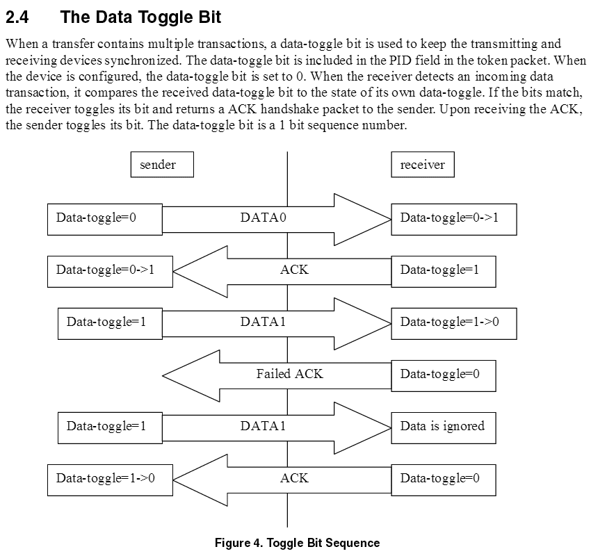
1) Let say that PC (host) send data over bidirectional EP1 (cdc, bulk) to KL27 (device). Device receive [OUT] token done, but where this DATA0 (data-toggle=0) value from host is stored on device side. Device "know" that it should be DATA0 (after completed enumeration), but where is host DATA value written to compare it with expected value on KL27 side? In KL27 RM it is noted that DATA0/1 field can not be modified by USBFS, only by KL27 program.
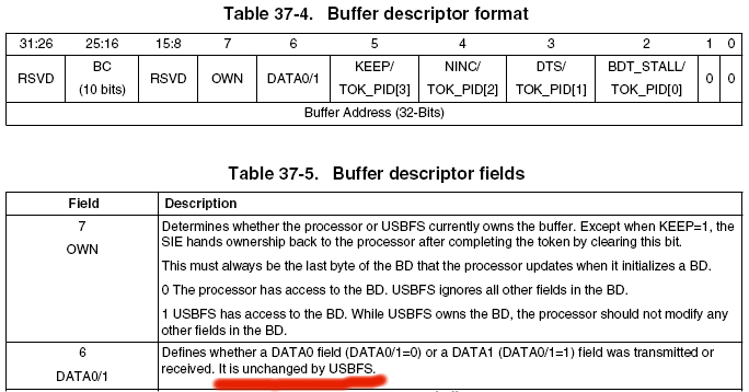
I can't find in KL27 SDK USB source anywhere checking for DATA0/1 values (between host and device) and recovery process after failed transfer (lost synchronization).
2) Let say that KL27 (device) send data to PC (host) over bidirectional EP1 (cdc, bulk). This DATA0/1 is another one, as I can see from KL27 SDK USB source, bidirectional EP have two DATA0/1 values (Data1[RX] and Data1[TX]). After completed enumeration, device will send data packet to host with DATA0, and host will respond with [IN] token done. Where is stored DATA value from host that can be checked on KL27 side? Again, In KL27 RM it is noted that DATA0/1 field can not be modified by USBFS, only by KL27 program.
Regards,
Josip

- Mark as New
- Bookmark
- Subscribe
- Mute
- Subscribe to RSS Feed
- Permalink
- Report Inappropriate Content
Josip
In order to better understand the operation I would suggest you do the following:
1. Clone the open source uTasker project from GitHub and build the KL27 target in Visual Studio (with USB_INTERACE and USE_USB_CDC enabled) - there are guides and videos showing how to do this (either with or without USB_SIMPLEX_ENDPOINTS enabled if you want to work with shared bulk endpoint to not) - eg. search uTasker on Youtube.
2. Run its KL27 simulation in Visual Studio and command USB enumeration so that the device is enumerated
3. Set a break-point in the USB-OTG interrupt handler _usb_otg_isr()
4. Use the Port Sim menu to inject bulk endpoint test frames - eg. use the simulation script "CDC_Modbus_EP1.sim" to inject some data in Modbus ASCII format (the content itself is not important)
5. Now you can analyse the reception of multiple bulk data frames to see exactly how the data toggle works in the HW (this is simulated and if you want to understand more HW details you can look in the USB simulation code (see fnSimulateUSB()) that calls the interrupt to see it) and also how the firmware needs to react to it. The reference firmware works on all Kinetis FS OTG controllers and has been proven since 2008 on Coldfires and Kinetis and so represents one of the most reliable, efficient and accurate implementations available, allowing immediate solutions or else for educational purposes and as reference for correcting alternative developments.
Basically the reception works like this (assuming you have initialised the endpoint's buffer to receive even frames to its even buffer and odd frames to its odd buffer):
- The first bulk reception that you will receive on endpoint 1 after enumeration will arrive in the buffer descriptor's "even" buffer. You will find that the STAT register doesn't have the ODD BANK flag set so you know that the data was put into the even buffer.
- your code will process the content and set the OWN flag again so that subsequent frames can be received to it. The data flag will not need to be adjusted since it is already synchronised.
- The second bulk reception that you will receive will be to the buffer descriptor's odd buffer. You will find that the STAT register has the ODD BANK flag set so you know that the data was put into the odd buffer.
- your code will process the content and set the OWN flag again so that subsequent frames can be received to it. The data flag will not need to be adjusted since it is already synchronised.
This means that for data reception on a pure bulk endpoint nothing can really go wrong if you just toggle between the two buffers (according to the STAT register flag): The USB controller will only put even frames into the even buffer and odd frames into the odd buffer (no firmware handling of errors needed).
Endpoints used for control are more complicated since the buffers are used to receive also control frames and bulk frames and need to be resynchronised after each setup reception. The even and odd buffers can then be used in an inverted sense (depending on the implementation) but a solution can be seen in the reference code based on the use of a flag called CONTROL_DATA_TOGGLE_REVERSED which indicates that the odd buffer is presently being used for even buffer reception.
Transmission is more or less the same but in the other sense, whereby the data toggling is purely under firmware control. On a purely bulk endpoint one can set up the buffer descriptor's even buffer for DATA 0 and the odd buffer descriptor for DATA 1 and just toggle between the two, whereby the first after enumeration is a DATA 0 type (send from the even buffer).
One basic thing to understand is that there are two buffers for Rx and two for Tx that are associated with each endpoint (when one endpoint is used for both IN and OUT directions). These operate in a ping-pong style so that the next data can be prepared while present data is being transmitted, or so that next data can be received while present data is being handled.
Each of these buffers can be assigned to DATA 0 or DATA 1 frames and this will already control the reception (no handling of out-of-sequence data is needed since it can't occur). The firmware's job is to ensure that the DATA flag assigned to each buffer's control word is correct so that the reception operates smoothly (pure bulk endpoints just need to be set up and that was it) and transmission toggles correctly. Data transmission is usually a little more complicated since the firmware can make mistakes in its use of the toggling which could cause the host to completely ignore data when it goes wrong.
The even and odd buffers however are not tied to data 0/data 1 - this is under control of the buffer descriptor's control word and so can be swapped (either intentionally or un-intentionally...).
Regards
Mark
[uTasker project developer for Kinetis and i.MX RT]
Developer of USB for Luminary Micro, Atmel SAM7 and AVR32, STM32, Coldfire, LPC2xxx, LPC17XX, Kinetis and i.MX RT
- Mark as New
- Bookmark
- Subscribe
- Mute
- Subscribe to RSS Feed
- Permalink
- Report Inappropriate Content
"I can't find in KL27 SDK USB source anywhere checking for DATA0/1 values (between host and device) and recovery process after failed transfer (lost synchronization)."
They erroneously assume USB will be error free and don't address it.
A host driver may try on its end.
On Windows after ten failed attempts the device will be detached.
- Mark as New
- Bookmark
- Subscribe
- Mute
- Subscribe to RSS Feed
- Permalink
- Report Inappropriate Content
"DATA0/1 field can not be modified by USBFS, only by KL27 program."
The Freescale/NXP manual leaves a lot to be desired.
This document from Microchip has far better explanation.
See 27.3.5.3.4 Buffer Descriptor Format:
http://ww1.microchip.com/downloads/en/DeviceDoc/61126F.pdf
The USB core is a purchased IP from a third party so it shows up in different parts from different manufactures.
Bit-6 will be modified by the host on inbound PID.
- Mark as New
- Bookmark
- Subscribe
- Mute
- Subscribe to RSS Feed
- Permalink
- Report Inappropriate Content
Some of the documentation intermingles the USB Spec. Data Toggling of DATA0/1, with the parts double buffered Odd/Even pingponging. They have nothing to do with each other.
Disable the Data Toggle Synchronization (DTS) bit in the setup register and see if anything changes.
If things improve with that turned off, it means that DATA0/1 is out of phase at some point, or not in the expected initial state.
Bad idea to leave it turned off other than as a diagnostic. USB is not as error free as one would hope I have found.
