
- Forums
- Product Forums
- General Purpose MicrocontrollersGeneral Purpose Microcontrollers
- i.MX Forumsi.MX Forums
- QorIQ Processing PlatformsQorIQ Processing Platforms
- Identification and SecurityIdentification and Security
- Power ManagementPower Management
- Wireless ConnectivityWireless Connectivity
- RFID / NFCRFID / NFC
- Advanced AnalogAdvanced Analog
- Neural Processing UnitsNeural Processing Units
- MCX Microcontrollers
- S32G
- S32K
- S32V
- MPC5xxx
- Other NXP Products
- S12 / MagniV Microcontrollers
- Powertrain and Electrification Analog Drivers
- Sensors
- Vybrid Processors
- Digital Signal Controllers
- 8-bit Microcontrollers
- ColdFire/68K Microcontrollers and Processors
- PowerQUICC Processors
- OSBDM and TBDML
- S32M
- S32Z/E
-
- Solution Forums
- Software Forums
- MCUXpresso Software and ToolsMCUXpresso Software and Tools
- CodeWarriorCodeWarrior
- MQX Software SolutionsMQX Software Solutions
- Model-Based Design Toolbox (MBDT)Model-Based Design Toolbox (MBDT)
- FreeMASTER
- eIQ Machine Learning Software
- Embedded Software and Tools Clinic
- S32 SDK
- S32 Design Studio
- GUI Guider
- Zephyr Project
- Voice Technology
- Application Software Packs
- Secure Provisioning SDK (SPSDK)
- Processor Expert Software
- Generative AI & LLMs
-
- Topics
- Mobile Robotics - Drones and RoversMobile Robotics - Drones and Rovers
- NXP Training ContentNXP Training Content
- University ProgramsUniversity Programs
- Rapid IoT
- NXP Designs
- SafeAssure-Community
- OSS Security & Maintenance
- Using Our Community
-
- Cloud Lab Forums
-
- Knowledge Bases
- ARM Microcontrollers
- i.MX Processors
- Identification and Security
- Model-Based Design Toolbox (MBDT)
- QorIQ Processing Platforms
- S32 Automotive Processing Platform
- Wireless Connectivity
- CodeWarrior
- MCUXpresso Suite of Software and Tools
- MQX Software Solutions
- RFID / NFC
- Advanced Analog
- Neural Processing Units
-
- NXP Tech Blogs
- Home
- :
- 汎用マイクロコントローラ
- :
- Kinetisマイクロコントローラ
- :
- Re: MK60 SPI master doesn't receive
MK60 SPI master doesn't receive
- RSS フィードを購読する
- トピックを新着としてマーク
- トピックを既読としてマーク
- このトピックを現在のユーザーにフロートします
- ブックマーク
- 購読
- ミュート
- 印刷用ページ
MK60 SPI master doesn't receive
- 新着としてマーク
- ブックマーク
- 購読
- ミュート
- RSS フィードを購読する
- ハイライト
- 印刷
- 不適切なコンテンツを報告
Hi,
I have a problem with my SPI.
After analysing spi transaction using keil ulink pro debugger and I saw that information sent by SPI slave is not detected.
This is SPI configuration:
void SPI_Init(void) {
/*------------------------------------------------------------------------------
port SPI configuration
*------------------------------------------------------------------------------*/
SIM->SCGC5 |= SIM_SCGC5_PORTD_MASK; /* enable clock for PORTB */
SIM->SCGC3 |= SIM_SCGC3_SPI2_MASK; /* enable clock for SPI2 */
// Assign SPI signals to the port pins
PORTD->PCR[11] &= PORT_PCR_MUX_MASK;
PORTD->PCR[11] |= PORT_PCR_MUX(2) ; // SPI2 CS
PORTD->PCR[12] &= PORT_PCR_MUX_MASK;
PORTD->PCR[12] |= PORT_PCR_MUX(2) ; // SPI2 SCLK
PORTD->PCR[13] &= PORT_PCR_MUX_MASK;
PORTD->PCR[13] |= PORT_PCR_MUX(2) ; // SPI2 MOSI
PORTD->PCR[14] &= PORT_PCR_MUX_MASK;
PORTD->PCR[14] |= PORT_PCR_MUX(2) ; // SPI2 MISO
/*------------------------------------------------------------------------------
SPI register configuration (MCR Register, CTAR Register, SR Register)
*------------------------------------------------------------------------------*/
// Configuration
SPI2->MCR = SPI_MCR_HALT_MASK; // halt SPI before SPI setting psSPI->MCR = SPI_MCR_HALT_MASK
SPI2->MCR &= ~SPI_MCR_MDIS_MASK; // enable module
SPI2->MCR |= SPI_MCR_MSTR_MASK; // master mode enabled
SPI2->MCR |= SPI_MCR_PCSIS(1) // inactive state of CS signal is high
| SPI_MCR_DCONF(0)
| SPI_MCR_DIS_TXF_MASK // disable TX FIFO
| SPI_MCR_DIS_RXF_MASK; // Disable RX FIFO
SPI2->MCR |= SPI_MCR_ROOE_MASK;
// Setting the SPI protocol in order to match requirements of motor driver
SPI2->CTAR[0] = SPI_CTAR_PCSSCK(2) // PCS to SCK Delay Prescaler = 3
| SPI_CTAR_CSSCK(3) // PCS to SCK Delay Scaler = 4
| SPI_CTAR_PBR(1) // Baud Rate Prescaler = 2
| SPI_CTAR_PASC(3) // After SCK Delay Prescaler = 5
| SPI_CTAR_DT(2) // Delay After Transfer Scaler
| SPI_CTAR_BR(4) // Baud Rate Scaler = 512
| SPI_CTAR_ASC(3) // After SCK Delay Scaler
| SPI_CTAR_CPHA_MASK
| SPI_CTAR_PDT(1) // Delay after Transfer Prescaler = 7
| SPI_CTAR_CPOL_MASK // clock polarity - inactive state of SCK is high
| SPI_CTAR_FMSZ(7) ; // 9-bit transfer block
SPI2->SR = SPI_SR_TCF_MASK // clear transfert complet flag
| SPI_SR_EOQF_MASK // clear end of queue flag
| SPI_SR_TFUF_MASK // clear transmit FIFO Fill Flag
| SPI_SR_TFFF_MASK // clear transfert complet flag
| SPI_SR_RFOF_MASK // clear receive FIFO Overflow Flag
|SPI_SR_RFDF_MASK; // clear receive FIFO Drain Flag
SPI2->RSER = (uint32_t)0x00UL; // clear DMA interruptions
SPI2->MCR &= ~SPI_MCR_HALT_MASK; // starts DSPI transfers
}
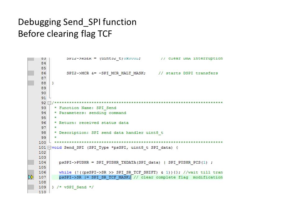
/*************************************************************************
* Function Name: SPI_Send
* Parameters: sending command
*
* Return: received status data
*
* Description: SPI send data handler uint8_t
*
*************************************************************************/
void Send_SPI (SPI_Type *psSPI, uint8_t SPI_data) {
psSPI->PUSHR = SPI_PUSHR_TXDATA(SPI_data) | SPI_PUSHR_PCS(1) ;
while (!((psSPI->SR >> SPI_SR_TCF_SHIFT) & 1)){}; //wait till transmission completes
psSPI->SR |= SPI_SR_TCF_MASK; // clear complete flag
} /* vSPI_Send */
uint8_t Receive_SPI (SPI_Type *psSPI) {
while (!(psSPI->SR & SPI_SR_RFDF_MASK));
return (psSPI->POPR);
} /* uchSPI_Receive */
This is my main.c :
#include "MK60N512MD100.h"
#include "spi.h"
/*----------------------------------------------------------------------------
MAIN function
*----------------------------------------------------------------------------*/
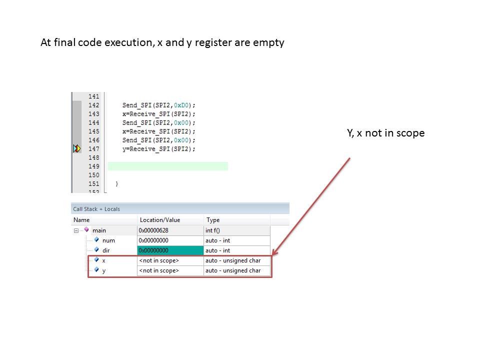
int main (void) {
uint8_t x,y;
SPI_Init();
while(1) {
Send_SPI(SPI2,0xD0);
x=Receive_SPI(SPI2);
Send_SPI(SPI2,0x00);
x=Receive_SPI(SPI2);
Send_SPI(SPI2,0x00);
y=Receive_SPI(SPI2);
}
}
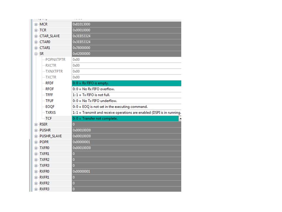
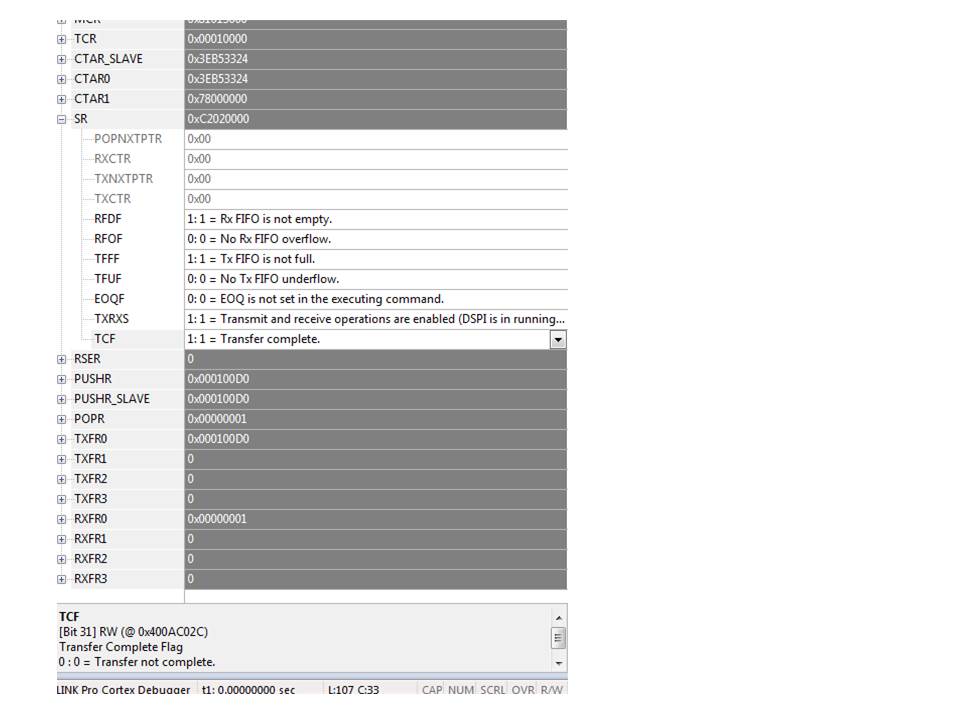
When I see SR register of SPI2, I realize that the flag RFDF is clear when the folloging part is executed:
psSPI->SR |= SPI_SR_TCF_MASK;
Thanks very much
- 新着としてマーク
- ブックマーク
- 購読
- ミュート
- RSS フィードを購読する
- ハイライト
- 印刷
- 不適切なコンテンツを報告
Thanks
- 新着としてマーク
- ブックマーク
- 購読
- ミュート
- RSS フィードを購読する
- ハイライト
- 印刷
- 不適切なコンテンツを報告
Hi enna salazar,
I'd like to highly recommend that you should get to understand the communication protocol of the slave device totally through review its datasheet.
I've attached a demo of TWR-K60D100 board about SPI communicate with external flash chips AT26DF081A and I think it help you to establish the connection between the Master and Slave correctly.
Have a great day,
Ping
-----------------------------------------------------------------------------------------------------------------------
Note: If this post answers your question, please click the Correct Answer button. Thank you!
-----------------------------------------------------------------------------------------------------------------------