
- Forums
- Product Forums
- General Purpose MicrocontrollersGeneral Purpose Microcontrollers
- i.MX Forumsi.MX Forums
- QorIQ Processing PlatformsQorIQ Processing Platforms
- Identification and SecurityIdentification and Security
- Power ManagementPower Management
- Wireless ConnectivityWireless Connectivity
- RFID / NFCRFID / NFC
- Advanced AnalogAdvanced Analog
- Neural Processing UnitsNeural Processing Units
- MCX Microcontrollers
- S32G
- S32K
- S32V
- MPC5xxx
- Other NXP Products
- S12 / MagniV Microcontrollers
- Powertrain and Electrification Analog Drivers
- Sensors
- Vybrid Processors
- Digital Signal Controllers
- 8-bit Microcontrollers
- ColdFire/68K Microcontrollers and Processors
- PowerQUICC Processors
- OSBDM and TBDML
- S32M
- S32Z/E
-
- Solution Forums
- Software Forums
- MCUXpresso Software and ToolsMCUXpresso Software and Tools
- CodeWarriorCodeWarrior
- MQX Software SolutionsMQX Software Solutions
- Model-Based Design Toolbox (MBDT)Model-Based Design Toolbox (MBDT)
- FreeMASTER
- eIQ Machine Learning Software
- Embedded Software and Tools Clinic
- S32 SDK
- S32 Design Studio
- GUI Guider
- Zephyr Project
- Voice Technology
- Application Software Packs
- Secure Provisioning SDK (SPSDK)
- Processor Expert Software
- Generative AI & LLMs
-
- Topics
- Mobile Robotics - Drones and RoversMobile Robotics - Drones and Rovers
- NXP Training ContentNXP Training Content
- University ProgramsUniversity Programs
- Rapid IoT
- NXP Designs
- SafeAssure-Community
- OSS Security & Maintenance
- Using Our Community
-
- Cloud Lab Forums
-
- Knowledge Bases
- ARM Microcontrollers
- i.MX Processors
- Identification and Security
- Model-Based Design Toolbox (MBDT)
- QorIQ Processing Platforms
- S32 Automotive Processing Platform
- Wireless Connectivity
- CodeWarrior
- MCUXpresso Suite of Software and Tools
- MQX Software Solutions
- RFID / NFC
- Advanced Analog
- Neural Processing Units
-
- NXP Tech Blogs
- Home
- :
- i.MX Forums
- :
- i.MX Processors
- :
- PCIE link up failed when booting the kernel on IMX6QSD board
PCIE link up failed when booting the kernel on IMX6QSD board
- Subscribe to RSS Feed
- Mark Topic as New
- Mark Topic as Read
- Float this Topic for Current User
- Bookmark
- Subscribe
- Mute
- Printer Friendly Page
- Mark as New
- Bookmark
- Subscribe
- Mute
- Subscribe to RSS Feed
- Permalink
- Report Inappropriate Content
Hi, all:
Anybody knows the reason of PCIE link up failed when booting the kernel?
The EP device is fine and can running on other x86 platform.
The information during the booting is :
......
PMU: registered new PMU device of type 0
Static Power Management for Freescale i.MX6
wait mode is enabled for i.MX6
cpaddr = c0880000 suspend_iram_base=c0934000
PM driver module loaded
iMX6 PCIe PCIe RC mode imx_pcie_pltfm_probe entering.
PCIE: imx_pcie_pltfm_probe start link up.
link up failed, DB_R0:0x00aafa00, DB_R1:0x08200000!
IMX PCIe port: link down!
IMX usb wakeup probe
add wake up source irq 75
IMX usb wakeup probe
cpu regulator mode:ldo_enable
i.MXC CPU frequency driver
......
Solved! Go to Solution.
- Mark as New
- Bookmark
- Subscribe
- Mute
- Subscribe to RSS Feed
- Permalink
- Report Inappropriate Content
Hongxing, thank you for your response.
I use L3.0.35_4.1.0_130816_source.tar.gz downloaded from freescale's IMX6QSD platform resource website.
Now, the problem has been solved. The PCIe clock output was not enabled in the code when IMX6 worked as RC.
- Mark as New
- Bookmark
- Subscribe
- Mute
- Subscribe to RSS Feed
- Permalink
- Report Inappropriate Content
Hi leo,
I met the same problem with you, and got similar error:
......
iMX6 PCIe PCIe RC mode imx_pcie_pltfm_probe entering.
PCIE: imx_pcie_pltfm_probe start link up.
link up failed, DB_R0:0x002f0200, DB_R1:0x08200000!
IMX PCIe port: link down!
I used L3.0.35_4.1.0_130816_source.tar.gz, but the problem persisted. WHere can I enable the PCIe clock output? The kernel, or the source code?
- Mark as New
- Bookmark
- Subscribe
- Mute
- Subscribe to RSS Feed
- Permalink
- Report Inappropriate Content
Hi Xiaoqiang,
You can do it in the function "static int _clk_pcie_enable(struct clk *clk)" in the file "clock.c" in source code.
Set the "ANATOP_LVDS_CLK1_SRC_SATA" bit of the register "ANADIG_MISC1_REG" to enable the clock.
Good luck!
- Mark as New
- Bookmark
- Subscribe
- Mute
- Subscribe to RSS Feed
- Permalink
- Report Inappropriate Content
I checked the code and found the register "ANADIG_MISC1_REG" had been set.
static int clkpcie_enable(struct clk *clk)
{
unsigned int reg;
#ifndef CONFIG_IMX_PCIE_RC_MODE_IN_EP_RC_SYS
/* Activate LVDS CLK1 (the MiniPCIe slot clock input) */
reg = __raw_readl(ANADIG_MISC1_REG);
reg &= ~ANATOP_LVDS_CLK1_IBEN_MASK;
__raw_writel(reg, ANADIG_MISC1_REG);
reg = __raw_readl(ANADIG_MISC1_REG);
reg |= ANATOP_LVDS_CLK1_SRC_SATA;
__raw_writel(reg, ANADIG_MISC1_REG);
reg = __raw_readl(ANADIG_MISC1_REG);
reg |= ANATOP_LVDS_CLK1_OBEN_MASK;
__raw_writel(reg, ANADIG_MISC1_REG);
#endif
I can not detect any signal on pin 23,25,31,33 of mini pcie slot using signal Oscilloscope.
But during boot up, I can detect waveform for about one secend on pin 11 and 13.
Is this phenomenon normal?
- Mark as New
- Bookmark
- Subscribe
- Mute
- Subscribe to RSS Feed
- Permalink
- Report Inappropriate Content
This clk would turned off if the pcie link is failed to set-up.
You should mask the link-down handler codes if you want to measure the clk signals on clk1_np when the pcie link is down.
Richard
Best Regard
- Mark as New
- Bookmark
- Subscribe
- Mute
- Subscribe to RSS Feed
- Permalink
- Report Inappropriate Content
Thank you,I can get the regular waveform of clk, 100M Hz, by modifing code in the function
'static void clkpcie_disable'.But why the pcie link failed to set-up?
- Mark as New
- Bookmark
- Subscribe
- Mute
- Subscribe to RSS Feed
- Permalink
- Report Inappropriate Content
There is another story, what's the HW platform used by you?
- Mark as New
- Bookmark
- Subscribe
- Mute
- Subscribe to RSS Feed
- Permalink
- Report Inappropriate Content
My platform is MX6Q-SDP.
- Mark as New
- Bookmark
- Subscribe
- Mute
- Subscribe to RSS Feed
- Permalink
- Report Inappropriate Content
No anything else?
Such as the connector, mini-pcie2std-pcie adaptor and so on.
BTW, what's kinds of ep device used at your side?
As I know that there is only mini-pcie slot on imx6 SDP board, I suspect that the quality of the pcie signals are
damaged by the HW connection between your EP device and SDP board.
Otherwise,
I believe the debug path is to first look into board and system level types of issues. Specifically:
a) Visually inspect the traces from the transmitter to the receiver and ensure the ac-coupling capacitors are connected properly.
b) Check for any DC issues. Specifically take a volt meter and look at the resistance from the transmitter to the ac-coupling capacitor. Then, measure from the other side of the ac-coupling capacitor to the receiver. Check if there is any large DC resistance value.
c) Check to see that the power and ground on both sides of the link are the same. Again, using a voltmeter, check the voltage supplies at the transmitter with respect to ground. Then probe from the ground of the transmitter to the ground of the destination of the signal and see if there is any voltage difference.
The above is the basic start to the debug which should show any low level board issues..
- Mark as New
- Bookmark
- Subscribe
- Mute
- Subscribe to RSS Feed
- Permalink
- Report Inappropriate Content
Hi Hongxing,
My pcie problem has been solved.Freescale sent me a new board and pcie works well. Our board is broken on hardware level.Thanks for your help!
- Mark as New
- Bookmark
- Subscribe
- Mute
- Subscribe to RSS Feed
- Permalink
- Report Inappropriate Content
Great to know that.
- Mark as New
- Bookmark
- Subscribe
- Mute
- Subscribe to RSS Feed
- Permalink
- Report Inappropriate Content
I tested pcie by two methods, unfortunately, all failed.
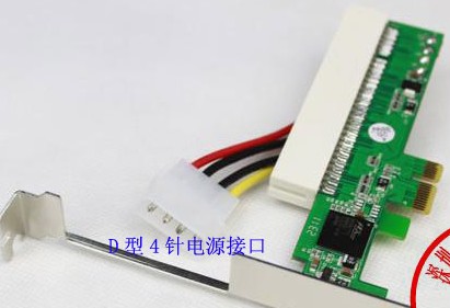
First, I used a pm2 mini-pcie2std-pcie adaptor and a pcie2pci adaptor(PEX8112):
Second,I tested mini-pcie wifi module(iwl4965) directly on the mini-pcie slot.
I checked the voltages on the slot using voltmeter,I found that 1.5V(pin6) was normal,but
3.3V was always changing.During boot up,it rose to 3.3V,but for a while, it begun to drop,
until to 2.x V, is this normal?
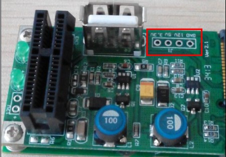
The mini-pcie2std-pcie don't need external power supply,its conversion circuit supplies power
to std-pcie.Severl days ago, these two solutions all worked well.But in order to use usb port on
the adaptor,I connected external power(12V and 5V,connected to std-pcie directly) to the place I
marked red,then the usb port could work well.I don't know if this is the problem,but after that,
I really haven't made the pcie work.
Any suggestion ?
- Mark as New
- Bookmark
- Subscribe
- Mute
- Subscribe to RSS Feed
- Permalink
- Report Inappropriate Content
what's the sw baseline used at your side?
Best Regards
Richard
- Mark as New
- Bookmark
- Subscribe
- Mute
- Subscribe to RSS Feed
- Permalink
- Report Inappropriate Content
Hongxing, thank you for your response.
I use L3.0.35_4.1.0_130816_source.tar.gz downloaded from freescale's IMX6QSD platform resource website.
Now, the problem has been solved. The PCIe clock output was not enabled in the code when IMX6 worked as RC.
- Mark as New
- Bookmark
- Subscribe
- Mute
- Subscribe to RSS Feed
- Permalink
- Report Inappropriate Content
Hi Leo:
It's great to hear that the problem had been fixed.
You're welcome. J
Best Regard
Richard
- Mark as New
- Bookmark
- Subscribe
- Mute
- Subscribe to RSS Feed
- Permalink
- Report Inappropriate Content
Hello richard.zhu,
I have tried to enable N6235 WiFi chip through PCIe using imx6 sabreauto board and Yocto but I have not success on this.
Please, could you check attached log and give your suggestions? After last message in console "iwlagn: Copyright(c) 2003-2011 Intel Corporation" the system does not respond and seem to be frozen.
Best Regards,
Abisai
- Mark as New
- Bookmark
- Subscribe
- Mute
- Subscribe to RSS Feed
- Permalink
- Report Inappropriate Content
Can you re-try the pcie wifi tests on imx_3.0.35 4.0 or 4.1 release?
BTW, what's kinds of sabreauto board used at your side?
Rev C or later version sabreauto obard is recommended.
Best Regards
Richard
- Mark as New
- Bookmark
- Subscribe
- Mute
- Subscribe to RSS Feed
- Permalink
- Report Inappropriate Content
Thanks a lot Richard, the problem was I had testing Rev B, Rev C works well.
- Mark as New
- Bookmark
- Subscribe
- Mute
- Subscribe to RSS Feed
- Permalink
- Report Inappropriate Content
Great.
Best Regards
Richard