
- Forums
- Product Forums
- General Purpose MicrocontrollersGeneral Purpose Microcontrollers
- i.MX Forumsi.MX Forums
- QorIQ Processing PlatformsQorIQ Processing Platforms
- Identification and SecurityIdentification and Security
- Power ManagementPower Management
- Wireless ConnectivityWireless Connectivity
- RFID / NFCRFID / NFC
- Advanced AnalogAdvanced Analog
- Neural Processing UnitsNeural Processing Units
- MCX Microcontrollers
- S32G
- S32K
- S32V
- MPC5xxx
- Other NXP Products
- S12 / MagniV Microcontrollers
- Powertrain and Electrification Analog Drivers
- Sensors
- Vybrid Processors
- Digital Signal Controllers
- 8-bit Microcontrollers
- ColdFire/68K Microcontrollers and Processors
- PowerQUICC Processors
- OSBDM and TBDML
- S32M
- S32Z/E
-
- Solution Forums
- Software Forums
- MCUXpresso Software and ToolsMCUXpresso Software and Tools
- CodeWarriorCodeWarrior
- MQX Software SolutionsMQX Software Solutions
- Model-Based Design Toolbox (MBDT)Model-Based Design Toolbox (MBDT)
- FreeMASTER
- eIQ Machine Learning Software
- Embedded Software and Tools Clinic
- S32 SDK
- S32 Design Studio
- GUI Guider
- Zephyr Project
- Voice Technology
- Application Software Packs
- Secure Provisioning SDK (SPSDK)
- Processor Expert Software
- Generative AI & LLMs
-
- Topics
- Mobile Robotics - Drones and RoversMobile Robotics - Drones and Rovers
- NXP Training ContentNXP Training Content
- University ProgramsUniversity Programs
- Rapid IoT
- NXP Designs
- SafeAssure-Community
- OSS Security & Maintenance
- Using Our Community
-
- Cloud Lab Forums
-
- Knowledge Bases
- ARM Microcontrollers
- i.MX Processors
- Identification and Security
- Model-Based Design Toolbox (MBDT)
- QorIQ Processing Platforms
- S32 Automotive Processing Platform
- Wireless Connectivity
- CodeWarrior
- MCUXpresso Suite of Software and Tools
- MQX Software Solutions
- RFID / NFC
- Advanced Analog
- Neural Processing Units
-
- NXP Tech Blogs
- Home
- :
- University Programs
- :
- University Programs Knowledge Base
- :
- Hints and Notes to Car Chassis assembly
Hints and Notes to Car Chassis assembly
- Subscribe to RSS Feed
- Mark as New
- Mark as Read
- Bookmark
- Subscribe
- Printer Friendly Page
- Report Inappropriate Content
Hints and Notes to Car Chassis assembly
Hints and Notes to Car Chassis assembly
On this page you will find additional notes to chassis assembly you may find useful. Examples of components used are obtained from the
http://www.soselectronic.com/ distributor.
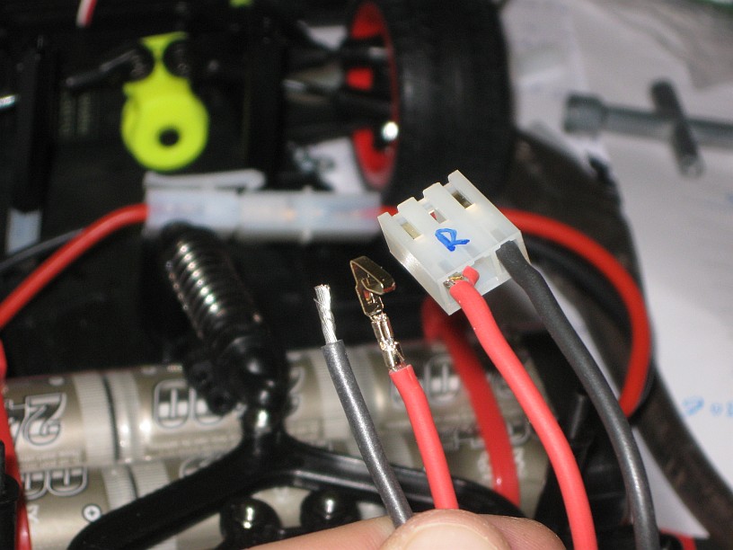
Cables
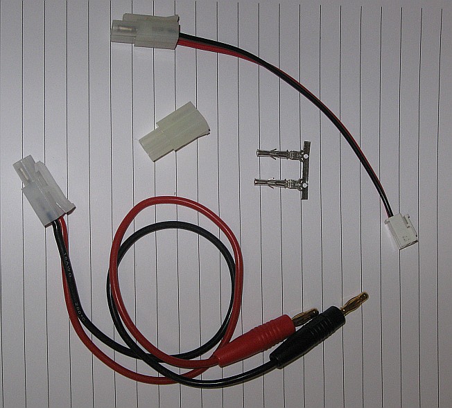
To connect battery you will need cable shown at the image top right. You can use the cable provided with the car and add an appropriate connector
to its end. This usually requires special crimping tool, so it may be more appropriate to buy the "Tamyia charging cable" (shown on the bottom left side
of the image above), cut the banana ends and attach the connector to the board. If you search for the appropriate type of the connector, it is
called usually Tamiya charging connector, Tamiya jack 6,3 mm (SOS code 70479) or similar.
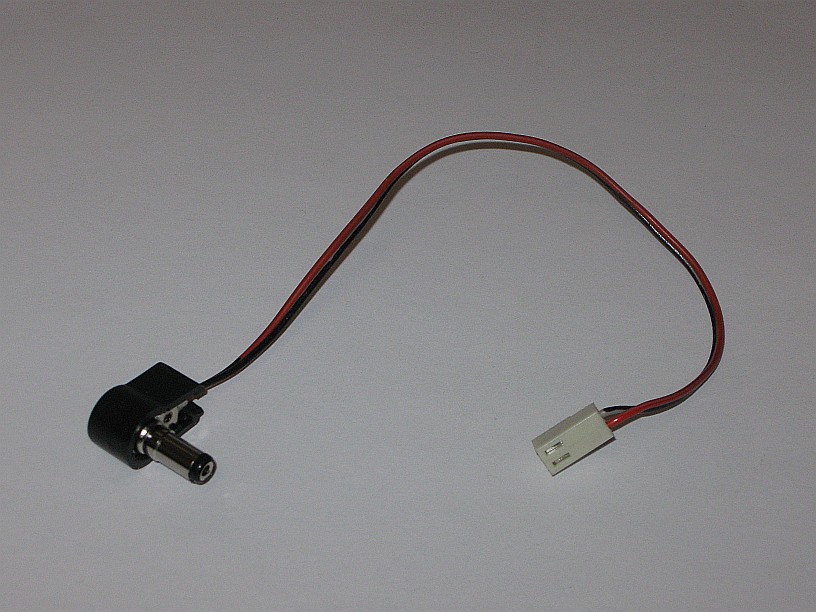
Another cable you have to assemble is a power supply cable for the microprocessor board. You will need approx. 10-15 cm long cable with the
barrel jack (SOS code 3834) or similar on one end and 2-pin 2.54mm connector (e.g. SOS code 4934 + 4937) on the other end.
NOTE: Never power the microprocessor board and interface boards from different power supplies! In such case the grounds on both boards are
not connected and you can damage the board. The grey flat ribbon cable that interconnects the boards is for signals only, there is no common
GND connection!
Battery
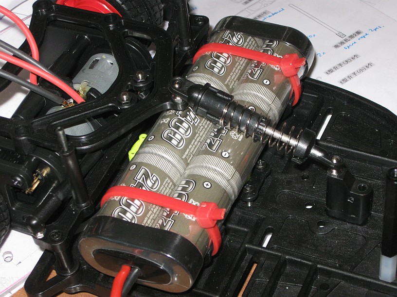
You may find (as we did) the provided cable strips too weak to hold the battery on the place. Replace them with the classic electricians cable strips
(e.g. SOS code 67504).
Also do not forget that the batteries need to be charged fully the first time you charge them or they will not be able to fully charge in the future. If you jump the gun because you want to test your code as soon as you can you will hurt yourself later as we found our battery was absolutely shot in later stages of our build.
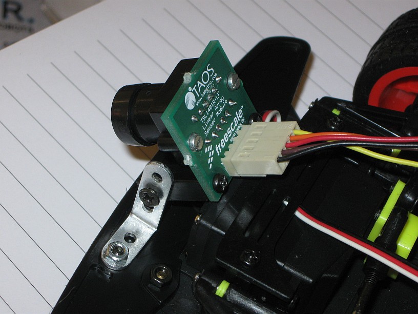
Motor wires
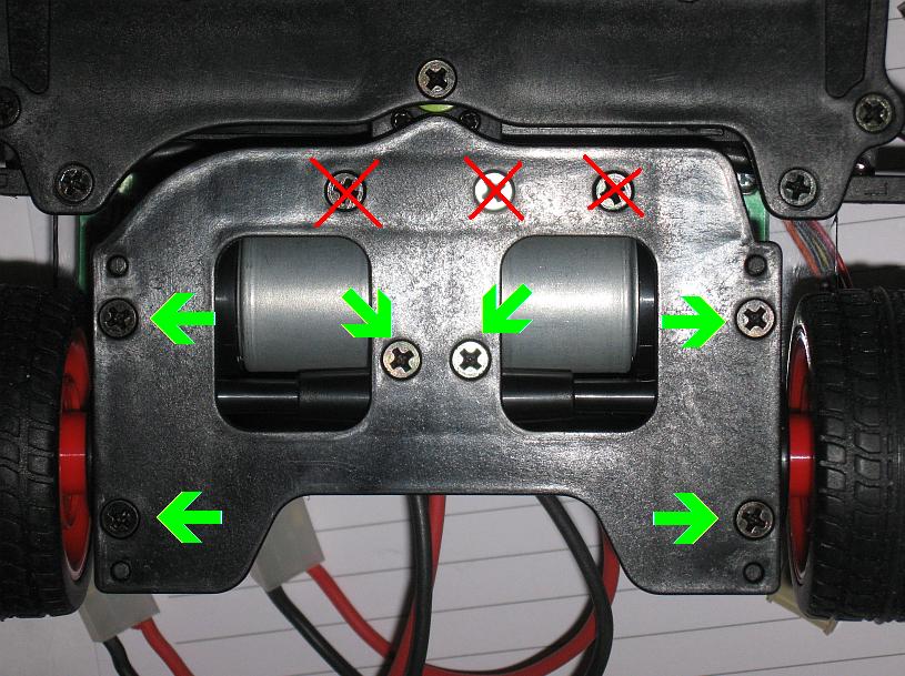
To attach the motor to the interface board you may find (as we did) the cables too short. Then remove 6 screws on the bottom (see image on the left),
open the motor box and desolder the short wires. Replace with approx. 15 cm long silicon cables at least 1mm2. End of the cables should be connected
to the 3-pin connectors with the 3,9mm pitch (e.g. SOS order code 5914 ) - see image on the right. Again, the contacts should be attached using a special crimp tool.
Camera
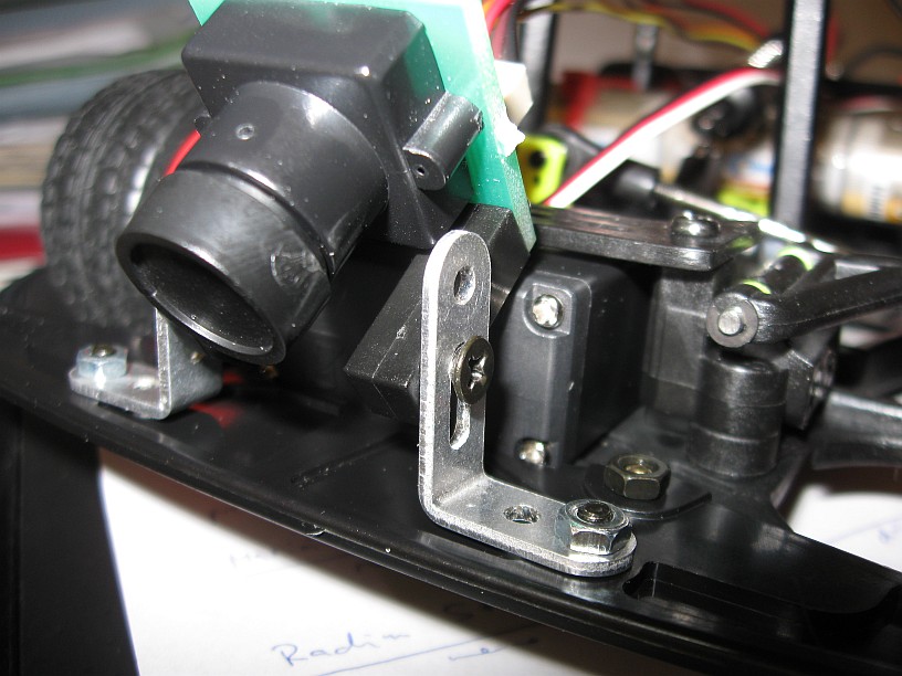
To attach the camera we found useful to prepare two metal L-shaped pieces made from aluminium. With the help of black plastic distance posts (already available in the kit) and these metal stands, you may freely change the position of the camera over the surface. You may use following files to cut the required shapes (drawing was made using the QCad program):
Base board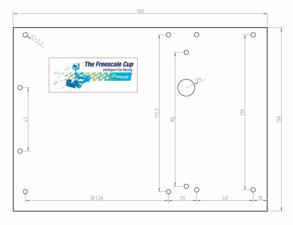
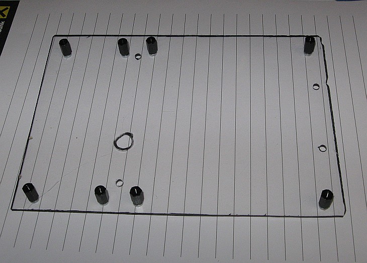
There was no motherboard in the kit, so you will need to provide your own. To make life easier, we offer you our CAD files created with QCad program. You may use it
to produce your board. We use plexiglass for ours, but any other plastic material is appropriate. The large hole in the middle is for cables from the servo. We attach the board to the car using the
plastic standoffs (you will need them 55 mm long, so in our case, we used the combination of 40 + 15 mm) - see an example (SOS code 10260).
To attach both the processor and interface boards the simillar 5mm plastic standoffs were used.
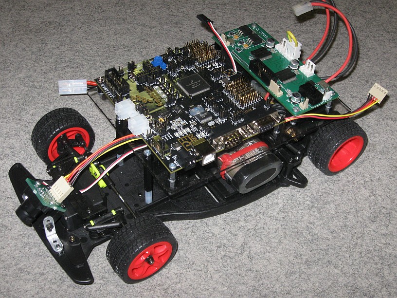
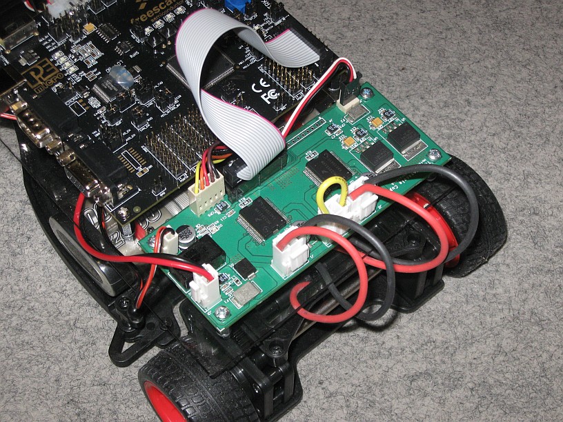
Getting all together
Please, notice the orientation of cables, especially the power supplies. You may find useful following connection diagram.
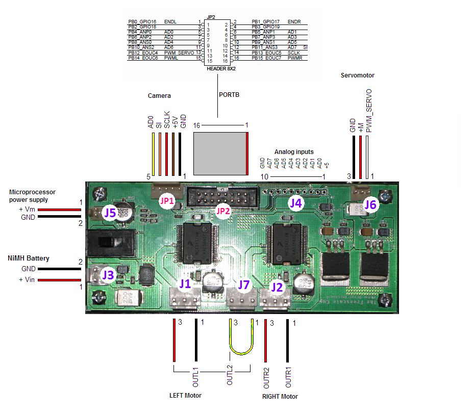
NOTE: Never power the microprocessor board and interface boards from different power supplies! In such case the grounds on both boards are
not connected and you can damage the board. The grey flat ribbon cable that interconnects the boards is for signals only, there is no common
GND connection!
Servo Motor connectors
The parts provided are extremely flimsy and if you snap them in and the wheels are not perfectly straight the wheels will align wrong when the servo first turns on. First off just concentrate on one wheel at a time and we found it useful to have one person hold the wheel straight while the arm was in the proper position and then we used needle nose pliers to quickly and precisely snap the pieces into the wheel. Don't be afraid to use some muscle we hesitated a few times at first because it didn't look good but it was fine.