
- Forums
- Product Forums
- General Purpose MicrocontrollersGeneral Purpose Microcontrollers
- i.MX Forumsi.MX Forums
- QorIQ Processing PlatformsQorIQ Processing Platforms
- Identification and SecurityIdentification and Security
- Power ManagementPower Management
- Wireless ConnectivityWireless Connectivity
- RFID / NFCRFID / NFC
- Advanced AnalogAdvanced Analog
- Neural Processing UnitsNeural Processing Units
- MCX Microcontrollers
- S32G
- S32K
- S32V
- MPC5xxx
- Other NXP Products
- S12 / MagniV Microcontrollers
- Powertrain and Electrification Analog Drivers
- Sensors
- Vybrid Processors
- Digital Signal Controllers
- 8-bit Microcontrollers
- ColdFire/68K Microcontrollers and Processors
- PowerQUICC Processors
- OSBDM and TBDML
- S32M
- S32Z/E
-
- Solution Forums
- Software Forums
- MCUXpresso Software and ToolsMCUXpresso Software and Tools
- CodeWarriorCodeWarrior
- MQX Software SolutionsMQX Software Solutions
- Model-Based Design Toolbox (MBDT)Model-Based Design Toolbox (MBDT)
- FreeMASTER
- eIQ Machine Learning Software
- Embedded Software and Tools Clinic
- S32 SDK
- S32 Design Studio
- GUI Guider
- Zephyr Project
- Voice Technology
- Application Software Packs
- Secure Provisioning SDK (SPSDK)
- Processor Expert Software
- Generative AI & LLMs
-
- Topics
- Mobile Robotics - Drones and RoversMobile Robotics - Drones and Rovers
- NXP Training ContentNXP Training Content
- University ProgramsUniversity Programs
- Rapid IoT
- NXP Designs
- SafeAssure-Community
- OSS Security & Maintenance
- Using Our Community
-
- Cloud Lab Forums
-
- Knowledge Bases
- ARM Microcontrollers
- i.MX Processors
- Identification and Security
- Model-Based Design Toolbox (MBDT)
- QorIQ Processing Platforms
- S32 Automotive Processing Platform
- Wireless Connectivity
- CodeWarrior
- MCUXpresso Suite of Software and Tools
- MQX Software Solutions
- RFID / NFC
- Advanced Analog
- Neural Processing Units
-
- NXP Tech Blogs
- Home
- :
- i.MX Forums
- :
- i.MX RT Crossover MCUs
- :
- RT1050 EVKB SPI Examples not working
RT1050 EVKB SPI Examples not working
- Subscribe to RSS Feed
- Mark Topic as New
- Mark Topic as Read
- Float this Topic for Current User
- Bookmark
- Subscribe
- Mute
- Printer Friendly Page

- Mark as New
- Bookmark
- Subscribe
- Mute
- Subscribe to RSS Feed
- Permalink
- Report Inappropriate Content
Edit: After further research I found that the SPI0 signals are not populated on the J24 Arduino header. See the comment marked as the solution.
I'm trying to get SPI working on the RT1050 EVKB boards using sample code from SDK V2.10.0.
I've got two boards setup. One running the lpspi driver demo [\polling_b2b\master] example and the other one running the slave version of that code.
I've hooked up the slave board to the master board correctly and the demo code absolutely doesn't work for me. I can see the debug messages on my serial ports for both the master and slave, but the master keeps saying the transfer failed and the slave never prints that it received data.
I literally used the sample AS IS without any modifications and I'm having no luck.
I went a step further and hooked up a logic analyzer ( Saleae logic 8 )
Does anybody have ANY idea what could be wrong?
Seems to me that at a minimum I should at least see the CLK and CS/SS lines showing valid behavior on the logic analyzer. I see absolutely no activity on any of the SPI pins.
I did verify that my logic analyzer is working by hooking up one channel to a blinking LED. The analyzer was properly detecting and showing the LED activity. And I also know that other channels are working on my analyzer.
I also did some cursory debugging and didn't notice any API calls failing...
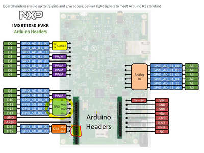
And to be sure I'm using the correct pins on the board, here is the diagram that I'm following. The pins I'm using are circled in red and are the SPI0 pins.
Thank you.
Jim Norton
Sr. Firmware Engineer - TransAct Technologies, Inc.
Solved! Go to Solution.
- Mark as New
- Bookmark
- Subscribe
- Mute
- Subscribe to RSS Feed
- Permalink
- Report Inappropriate Content
So I did some further research. The SPI0 on the Arduino header is shared with the SDCARD. From https://docs.rtems.org/branches/master/user/bsps/bsps-arm.html#id19
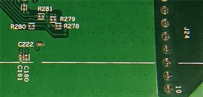
Note that the SPI-pins on the evaluation board are shared with the SD card. Populate R278, R279, R280, R281 on the IMXRT1050-EVKB (Rev A) to use the SPI pins on the Arduino connector.
I found the resistor footprints on the underside of the board under the sdcard.
Jim Norton
Sr. Firmware Engineer - TransAct Technologies, Inc.
- Mark as New
- Bookmark
- Subscribe
- Mute
- Subscribe to RSS Feed
- Permalink
- Report Inappropriate Content
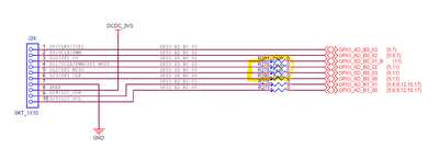
Does the RT1050 EVKB board come with SPI0 not connected to the Arduino header? See snippet of board schematic below.
Jim Norton
Sr. Firmware Engineer - TransAct Technologies, Inc.
- Mark as New
- Bookmark
- Subscribe
- Mute
- Subscribe to RSS Feed
- Permalink
- Report Inappropriate Content
So I did some further research. The SPI0 on the Arduino header is shared with the SDCARD. From https://docs.rtems.org/branches/master/user/bsps/bsps-arm.html#id19
Note that the SPI-pins on the evaluation board are shared with the SD card. Populate R278, R279, R280, R281 on the IMXRT1050-EVKB (Rev A) to use the SPI pins on the Arduino connector.
I found the resistor footprints on the underside of the board under the sdcard.
Jim Norton
Sr. Firmware Engineer - TransAct Technologies, Inc.
