
- Forums
- Product Forums
- General Purpose MicrocontrollersGeneral Purpose Microcontrollers
- i.MX Forumsi.MX Forums
- QorIQ Processing PlatformsQorIQ Processing Platforms
- Identification and SecurityIdentification and Security
- Power ManagementPower Management
- Wireless ConnectivityWireless Connectivity
- RFID / NFCRFID / NFC
- Advanced AnalogAdvanced Analog
- Neural Processing UnitsNeural Processing Units
- MCX Microcontrollers
- S32G
- S32K
- S32V
- MPC5xxx
- Other NXP Products
- S12 / MagniV Microcontrollers
- Powertrain and Electrification Analog Drivers
- Sensors
- Vybrid Processors
- Digital Signal Controllers
- 8-bit Microcontrollers
- ColdFire/68K Microcontrollers and Processors
- PowerQUICC Processors
- OSBDM and TBDML
- S32M
- S32Z/E
-
- Solution Forums
- Software Forums
- MCUXpresso Software and ToolsMCUXpresso Software and Tools
- CodeWarriorCodeWarrior
- MQX Software SolutionsMQX Software Solutions
- Model-Based Design Toolbox (MBDT)Model-Based Design Toolbox (MBDT)
- FreeMASTER
- eIQ Machine Learning Software
- Embedded Software and Tools Clinic
- S32 SDK
- S32 Design Studio
- GUI Guider
- Zephyr Project
- Voice Technology
- Application Software Packs
- Secure Provisioning SDK (SPSDK)
- Processor Expert Software
- Generative AI & LLMs
-
- Topics
- Mobile Robotics - Drones and RoversMobile Robotics - Drones and Rovers
- NXP Training ContentNXP Training Content
- University ProgramsUniversity Programs
- Rapid IoT
- NXP Designs
- SafeAssure-Community
- OSS Security & Maintenance
- Using Our Community
-
- Cloud Lab Forums
-
- Knowledge Bases
- ARM Microcontrollers
- i.MX Processors
- Identification and Security
- Model-Based Design Toolbox (MBDT)
- QorIQ Processing Platforms
- S32 Automotive Processing Platform
- Wireless Connectivity
- CodeWarrior
- MCUXpresso Suite of Software and Tools
- MQX Software Solutions
- RFID / NFC
- Advanced Analog
- Neural Processing Units
-
- NXP Tech Blogs
- Home
- :
- ソフトウェア・フォーラム
- :
- プロセッサ・エキスパート・ソフトウェア
- :
- SynchroMaster Bean for SPI use - SS line irregularities at different baud rates
SynchroMaster Bean for SPI use - SS line irregularities at different baud rates
- RSS フィードを購読する
- トピックを新着としてマーク
- トピックを既読としてマーク
- このトピックを現在のユーザーにフロートします
- ブックマーク
- 購読
- ミュート
- 印刷用ページ
SynchroMaster Bean for SPI use - SS line irregularities at different baud rates
- 新着としてマーク
- ブックマーク
- 購読
- ミュート
- RSS フィードを購読する
- ハイライト
- 印刷
- 不適切なコンテンツを報告
Hello,
I am developing for a MC9S12XDT512MAA processor. I am using CodeWarrior for S12x v5.2 - with imported processor derivatives for v5.1 (as v5.2 dropped support for this processor) via this method: How-to Add missing derivatives to CodeWarrior Classic HCS12(X) 5.2 (Unofficial Method)
I am taking over a project which is using Processor Expert to configure a SynchroMaster bean for SPI use. It is master only - not needing information from the slave - a Maxim MAX6951 display driver chip. The Maxim chip needs 16 bits of data during a transmission. I am sending three packets of 16 bits each to the chip. The Maxim chip can handle a clock period down to 38.4 nanoseconds.
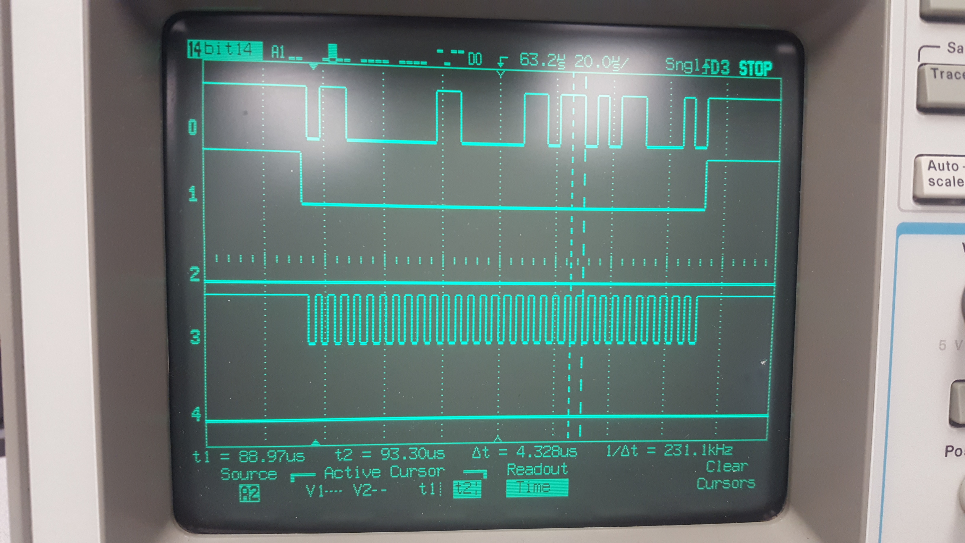
When the SynchroMaster shift clock rate is set to 1.085 microseconds (fastest shown on the list provided in PE), the SS line from the processor is toggled low only for 8 bits, then toggled high, and back low for the next 8 bits and continues for the rest of the transmission. All data is transmitted over the MOSI line. From this behavior, I am seeing incorrect data being displayed from the Maxim chip.
When setting the shift clock rate to 2.170 microseconds, CS is toggled low for 16 bits. All data over the MOSI line is transmitted and data is being displayed correctly from the Maxim chip.
When setting the shift clock rate to 4.340 microseconds, the CS line is toggled low for 32 bits continuously and then goes high. I am losing data in the transmission - only 32 of 48 expected bits are seen over the MOSI line.
When I only change the shift rate in PE and re-make the code, the only code that is changed is the generated C file, to which the baud rate initization is change (to be expected). So while no other code appears to be changing, I am getting wildly different results on the CS line.
/* SPI1BR: ??=0,SPPR2=0,SPPR1=0,SPPR0=0,??=0,SPR2=0,SPR1=0,SPR0=1 */
SPI1BR = 1U; /* Set the baud rate register */
Can anyone help explain why these different baud rates are causing the SPI driver to act differently? I am new to the CodeWarriror suite, and PE. Is there a place I can view the lower level (assembly?) code that is generated by PE? I have viewed the C code generated by PE, but it seems to be twiddling registers correctly.
Attached are pictures taken of the MOSI data line (line 0). SS line (line 1) and clock line (line 3).
-Matt