- Forums
- Product Forums
- General Purpose MicrocontrollersGeneral Purpose Microcontrollers
- i.MX Forumsi.MX Forums
- QorIQ Processing PlatformsQorIQ Processing Platforms
- Identification and SecurityIdentification and Security
- Power ManagementPower Management
- Wireless ConnectivityWireless Connectivity
- RFID / NFCRFID / NFC
- MCX Microcontrollers
- S32G
- S32K
- S32V
- MPC5xxx
- Other NXP Products
- S12 / MagniV Microcontrollers
- Powertrain and Electrification Analog Drivers
- Sensors
- Vybrid Processors
- Digital Signal Controllers
- 8-bit Microcontrollers
- ColdFire/68K Microcontrollers and Processors
- PowerQUICC Processors
- OSBDM and TBDML
- S32M
-
- Solution Forums
- Software Forums
- MCUXpresso Software and ToolsMCUXpresso Software and Tools
- CodeWarriorCodeWarrior
- MQX Software SolutionsMQX Software Solutions
- Model-Based Design Toolbox (MBDT)Model-Based Design Toolbox (MBDT)
- FreeMASTER
- eIQ Machine Learning Software
- Embedded Software and Tools Clinic
- S32 SDK
- S32 Design Studio
- GUI Guider
- Zephyr Project
- Voice Technology
- Application Software Packs
- Secure Provisioning SDK (SPSDK)
- Processor Expert Software
-
- Topics
- Mobile Robotics - Drones and RoversMobile Robotics - Drones and Rovers
- NXP Training ContentNXP Training Content
- University ProgramsUniversity Programs
- Rapid IoT
- NXP Designs
- SafeAssure-Community
- OSS Security & Maintenance
- Using Our Community
-
- Cloud Lab Forums
-
- Knowledge Bases
- ARM Microcontrollers
- i.MX Processors
- Identification and Security
- Model-Based Design Toolbox (MBDT)
- QorIQ Processing Platforms
- S32 Automotive Processing Platform
- Wireless Connectivity
- CodeWarrior
- MCUXpresso Suite of Software and Tools
- MQX Software Solutions
-
- Home
- :
- Product Forums
- :
- MPC5xxx
- :
- Having trouble reading multi-channel ADC data with DMA.
Having trouble reading multi-channel ADC data with DMA.
- Subscribe to RSS Feed
- Mark Topic as New
- Mark Topic as Read
- Float this Topic for Current User
- Bookmark
- Subscribe
- Mute
- Printer Friendly Page
Having trouble reading multi-channel ADC data with DMA.
- Mark as New
- Bookmark
- Subscribe
- Mute
- Subscribe to RSS Feed
- Permalink
- Report Inappropriate Content
Hi,
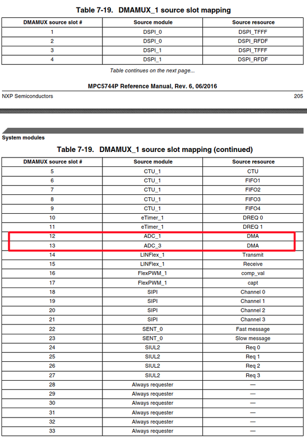
I am using MPC5744p and having trouble reading multi-channel ADC data with DMA. When only one channel is active, I can access the data with DMA without any problems but I have problem when I try to access multiple ADC channels with multiple DMA channels. While all values written to the buffer in ram are valid when single channel is active, this is not the case in multi-channel. I shared the DMA init function and related images.
Additionally, do you have any sample codes or any documents you can recommend for using hw triggered multi-channel DMA?
uint32_t adc_arr2[100];
uint32_t adc_arr1[100];

static void dmamux_init(volatile struct DMAMUX_tag *dma_mux_p, uint8_t dmamux_source, uint8_t dma_ch)
{
	dma_mux_p->CHCFG[dma_ch].B.ENBL = 1;
	dma_mux_p->CHCFG[dma_ch].B.SOURCE = dmamux_source;
	dma_mux_p->CHCFG[dma_ch].B.TRIG = 0;
}

void dma_0_init(void)
{
	// DMAMUX_1 configuration for ADC trigger
	dmamux_init(&DMAMUX_1, 0xC, 1);    //dma0 channel 17 init
	dmamux_init(&DMAMUX_1, 0xC, 2);    //dma0 channel 18 init

	DMA_0.ERQ.B.ERQ17 = 1;    //The DMA request signal for channel 17
	DMA_0.ERQ.B.ERQ18 = 1;    //The DMA request signal for channel 18

	DMA_0.TCD[17].SADDR.R = ((vuint32_t) &ADC_1.CDR[1].R);    //Source Address ADC1_AN[1]
	DMA_0.TCD[17].ATTR.R = 0x0 | 0x200 | 0x0 | 0x2;    //Source transfer size 32-bit, no Address Modulo used
	DMA_0.TCD[17].SOFF.R = 0;    // TCD Signed Source Address Offset(constant)
	DMA_0.TCD[17].NBYTES.MLNO.R = 4;    //Minor Byte Count: 4byte
	DMA_0.TCD[17].SLAST.R = 0;    //TCD Last Source Address Adjustment
	DMA_0.TCD[17].DOFF.R = 4;
	DMA_0.TCD[17].DADDR.R = (vuint32_t) &adc_arr2[0];	 //Destination Address
	DMA_0.TCD[17].CITER.ELINKNO.R = 100;
	DMA_0.TCD[17].DLASTSGA.R = -400;    // Destination last address adjustment -(4byte*100 element)
	DMA_0.TCD[17].BITER.ELINKNO.R = 100;
	DMA_0.TCD[17].CSR.B.INTMAJOR = 1;
	DMA_0.TCD[17].CSR.B.DREQ = 1;

	DMA_0.TCD[18].SADDR.R = ((vuint32_t) &ADC_1.CDR[2].R);    //Source Address ADC1_AN[2]
	DMA_0.TCD[18].ATTR.R = 0x0 | 0x200 | 0x0 | 0x2;    //Source transfer size 32-bit, no Address Modulo used
	DMA_0.TCD[18].SOFF.R = 0;
	DMA_0.TCD[18].NBYTES.MLNO.R = 4;
	DMA_0.TCD[18].SLAST.R = 0;
	DMA_0.TCD[18].DOFF.R = 4;
	DMA_0.TCD[18].DADDR.R = (vuint32_t) &adc_arr1[0];	 //Destination Address
	DMA_0.TCD[18].CITER.ELINKNO.R = 100;
	DMA_0.TCD[18].DLASTSGA.R = -400;    // Destination last address adjustment
	DMA_0.TCD[18].BITER.ELINKNO.R = 100;
	DMA_0.TCD[18].CSR.B.INTMAJOR = 1;
	DMA_0.TCD[18].CSR.B.DREQ = 1;

	DMA_0.CR.R = 0xC;    //round robin is used

	INTC_0.PSR[70].R = 0x801F;    //set interrupt priority
	INTC_0.PSR[71].R = 0x801F;    //set interrupt priority
}

void dma_ch18_major_completed_isr(void)
{
	//there is a breakpoint in here to see content of the array
	DMA_0.ERQ.B.ERQ18 = 1;
	DMA_0.INT.B.INT18 = 1;
}
void dma_ch17_major_completed_isr(void)
{
	//there is a breakpoint in here to see content of the array
	DMA_0.ERQ.B.ERQ17 = 1;
	DMA_0.INT.B.INT17 = 1;
}- Mark as New
- Bookmark
- Subscribe
- Mute
- Subscribe to RSS Feed
- Permalink
- Report Inappropriate Content
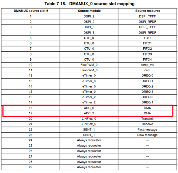
Hi, for result draining you have to use ADC DMA source. Your configuration is incorrect.
- Mark as New
- Bookmark
- Subscribe
- Mute
- Subscribe to RSS Feed
- Permalink
- Report Inappropriate Content
Thanks for your feedback.
Actually, i initialized for adc1 and dma as below. Where exactly is the problem?
// DMAMUX_1 configuration for ADC trigger
dmamux_init(&DMAMUX_1, 12, 1); //ADC1 source slot 12, dma channel 17 init
dmamux_init(&DMAMUX_1, 12, 2); //ADC1 source slot 12, dma channel 18 init- Mark as New
- Bookmark
- Subscribe
- Mute
- Subscribe to RSS Feed
- Permalink
- Report Inappropriate Content
I am sorry, I have somehow overlooked it. This is actually right.
But you have another issue there - you cannot route one DMA source to multiple DMA channels.
Use one channel for both result readings, or two linked channels, or scatter-gather feature.
- Mark as New
- Bookmark
- Subscribe
- Mute
- Subscribe to RSS Feed
- Permalink
- Report Inappropriate Content
I faced with same problem. I initialized DMA sucessfully. ADC works with DMA properly.
But I have trouble get DMA working from several channel. How can we achieve exact solution, could you help me for that? @davidtosenovjan @Muhammet


