
- Forums
- Product Forums
- General Purpose MicrocontrollersGeneral Purpose Microcontrollers
- i.MX Forumsi.MX Forums
- QorIQ Processing PlatformsQorIQ Processing Platforms
- Identification and SecurityIdentification and Security
- Power ManagementPower Management
- Wireless ConnectivityWireless Connectivity
- RFID / NFCRFID / NFC
- Advanced AnalogAdvanced Analog
- Neural Processing UnitsNeural Processing Units
- MCX Microcontrollers
- S32G
- S32K
- S32V
- MPC5xxx
- Other NXP Products
- S12 / MagniV Microcontrollers
- Powertrain and Electrification Analog Drivers
- Sensors
- Vybrid Processors
- Digital Signal Controllers
- 8-bit Microcontrollers
- ColdFire/68K Microcontrollers and Processors
- PowerQUICC Processors
- OSBDM and TBDML
- S32M
- S32Z/E
-
- Solution Forums
- Software Forums
- MCUXpresso Software and ToolsMCUXpresso Software and Tools
- CodeWarriorCodeWarrior
- MQX Software SolutionsMQX Software Solutions
- Model-Based Design Toolbox (MBDT)Model-Based Design Toolbox (MBDT)
- FreeMASTER
- eIQ Machine Learning Software
- Embedded Software and Tools Clinic
- S32 SDK
- S32 Design Studio
- GUI Guider
- Zephyr Project
- Voice Technology
- Application Software Packs
- Secure Provisioning SDK (SPSDK)
- Processor Expert Software
- Generative AI & LLMs
-
- Topics
- Mobile Robotics - Drones and RoversMobile Robotics - Drones and Rovers
- NXP Training ContentNXP Training Content
- University ProgramsUniversity Programs
- Rapid IoT
- NXP Designs
- SafeAssure-Community
- OSS Security & Maintenance
- Using Our Community
-
- Cloud Lab Forums
-
- Knowledge Bases
- ARM Microcontrollers
- i.MX Processors
- Identification and Security
- Model-Based Design Toolbox (MBDT)
- QorIQ Processing Platforms
- S32 Automotive Processing Platform
- Wireless Connectivity
- CodeWarrior
- MCUXpresso Suite of Software and Tools
- MQX Software Solutions
- RFID / NFC
- Advanced Analog
- Neural Processing Units
-
- NXP Tech Blogs
- Home
- :
- General Purpose Microcontrollers
- :
- Kinetis Microcontrollers
- :
- Re: Bring up issues with K60DN512Z and JTAG
Bring up issues with K60DN512Z and JTAG
- Subscribe to RSS Feed
- Mark Topic as New
- Mark Topic as Read
- Float this Topic for Current User
- Bookmark
- Subscribe
- Mute
- Printer Friendly Page
- Mark as New
- Bookmark
- Subscribe
- Mute
- Subscribe to RSS Feed
- Permalink
- Report Inappropriate Content
Hello,
I recently inherited a project that I need to get up and running from bare metal. We are using a K60DN512Z mcu and connecting JTAG directly.
We are using PEmicro Multilink , Codewarrior 10.2 and a K60 Tower dev board.
The original code was written and tested on the tower, and I can hook up the multilink via JTAG to the tower and program, pause and run without any problem.
I really am not familiar with codewarrior, but have figured out enough to verify I have a working path between the pc and the K60 tower.
When I hook up the multilink to our product, which just came in, is where issues arise.
I have mcu reset tied to jtag, as well as TDI, TDO, TMS, and TCLK.
EZP_CS is pulled high via a 2.2K resistor. I hold down reset and then turn on the board and then after 1-2sec let go of reset. Led goes dim.
When using codewarrior to try to program the board, the reset light flashes, and clearly one can see on the scope trace reset going low.
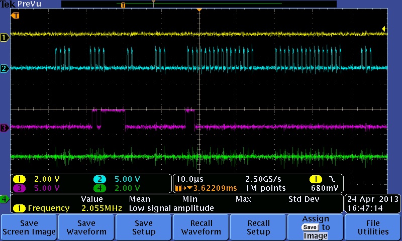
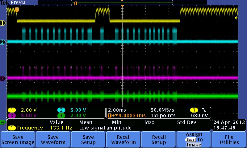
On the scope trace I have top to bottom, RESET,TCLK,TDI,TDO As can be seen I get nothing out from the mcu.
First picture is zoom in of first clocking activity after reset goes low.
Second picture is overall reset and clock, tdi activity.
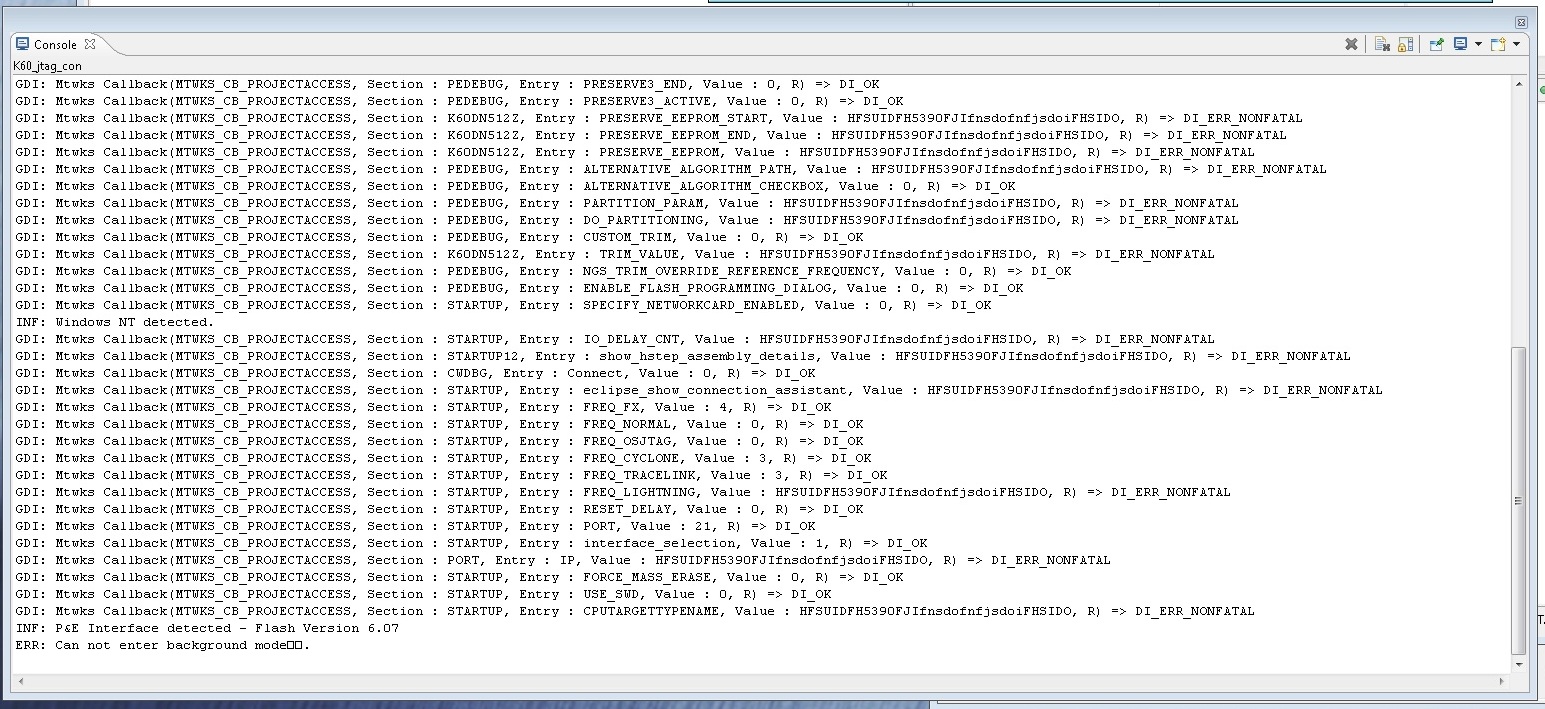
Third picture is PE micro info window from codewarrior. I can not seem to get the output to stay, it goes away after I abort the P&E connection assistant. Very annoying, if anyone knows how to save the error info from the console that too would be great!
The HFSUID info is odd, as is the fact "Cannot enter background mode"
Any and all help would be greatly appreciated!
Thanks!!
Solved! Go to Solution.
- Mark as New
- Bookmark
- Subscribe
- Mute
- Subscribe to RSS Feed
- Permalink
- Report Inappropriate Content
We found that the pcb mfg screwed up the soldermask causing some very subtle shorting so JTAG wouldn't work.
On secondary note, we tried to program the board with a p&e micro multilink universal. Didn't work. Their tech support tried to be helpful, but we ended up getting a segger J-link. First go and it programmed just fine.
- Mark as New
- Bookmark
- Subscribe
- Mute
- Subscribe to RSS Feed
- Permalink
- Report Inappropriate Content
Well that was too hopeful. We have the processor up and running. The EZP_CS line is critical to be set the right way. MQX isn't running, however a quick heartbeat and serial program via Processor Expert work fine! Off the the MQX forum to see if I can figure out why mqx won't work. Its always something!
Edit: CRITICAL if you are using MQX the RTC has to be working or things will not run. In our case RTC was not getting 3.3V. wrong diode package was installed on the board. FYI.
- Mark as New
- Bookmark
- Subscribe
- Mute
- Subscribe to RSS Feed
- Permalink
- Report Inappropriate Content
We found that the pcb mfg screwed up the soldermask causing some very subtle shorting so JTAG wouldn't work.
On secondary note, we tried to program the board with a p&e micro multilink universal. Didn't work. Their tech support tried to be helpful, but we ended up getting a segger J-link. First go and it programmed just fine.
- Mark as New
- Bookmark
- Subscribe
- Mute
- Subscribe to RSS Feed
- Permalink
- Report Inappropriate Content
Hello charles,
Well i had the similar problem getting my own board working. I used pe micro multilink jtag adapter. I used to get the same error "Cannot Enter Background Mode". I also verifed JTAG Pins all were working. After so many days and testing i found that EZP_CS should be disconnected from JTAG pins and should be pulled high, if its not high then according to documentation it will not work as all cores are locked. So as soon as i disconnected EZP_CS from jtag pins and pulled that pin to 3 volts. It started working.
Hope it helps
Regards
- Mark as New
- Bookmark
- Subscribe
- Mute
- Subscribe to RSS Feed
- Permalink
- Report Inappropriate Content
Hi,
Where in the documentation does it say I need to Pull EZP_CS High ?
Mine is floating and my JTAG is not working.
Also the Reset Pin seems to output voltage.
- Mark as New
- Bookmark
- Subscribe
- Mute
- Subscribe to RSS Feed
- Permalink
- Report Inappropriate Content
Hi Muhammad,
Thank you for the hint with EZP_CS. Unfortunately as I had mentioned in my post, I already have EZP_CS pulled high via a 2.2K resistor. Pin is verified as high when the board is powered up. Needless to say this is the least friendly embedded cpu I have ever had the pleasure to work with.
Just out of curiosity what value did you use to pull EZP_CS high??
thanks!