
- Forums
- Product Forums
- General Purpose MicrocontrollersGeneral Purpose Microcontrollers
- i.MX Forumsi.MX Forums
- QorIQ Processing PlatformsQorIQ Processing Platforms
- Identification and SecurityIdentification and Security
- Power ManagementPower Management
- MCX Microcontrollers
- S32G
- S32K
- S32V
- MPC5xxx
- Other NXP Products
- Wireless Connectivity
- S12 / MagniV Microcontrollers
- Powertrain and Electrification Analog Drivers
- Sensors
- Vybrid Processors
- Digital Signal Controllers
- 8-bit Microcontrollers
- ColdFire/68K Microcontrollers and Processors
- PowerQUICC Processors
- OSBDM and TBDML
-
- Solution Forums
- Software Forums
- MCUXpresso Software and ToolsMCUXpresso Software and Tools
- CodeWarriorCodeWarrior
- MQX Software SolutionsMQX Software Solutions
- Model-Based Design Toolbox (MBDT)Model-Based Design Toolbox (MBDT)
- FreeMASTER
- eIQ Machine Learning Software
- Embedded Software and Tools Clinic
- S32 SDK
- S32 Design Studio
- GUI Guider
- Zephyr Project
- Voice Technology
- Application Software Packs
- Secure Provisioning SDK (SPSDK)
- Processor Expert Software
- MCUXpresso Training Hub
-
- Topics
- Mobile Robotics - Drones and RoversMobile Robotics - Drones and Rovers
- NXP Training ContentNXP Training Content
- University ProgramsUniversity Programs
- Rapid IoT
- NXP Designs
- SafeAssure-Community
- OSS Security & Maintenance
- Using Our Community
-
- Cloud Lab Forums
-
- Knowledge Bases
- ARM Microcontrollers
- i.MX Processors
- Identification and Security
- Model-Based Design Toolbox (MBDT)
- QorIQ Processing Platforms
- S32 Automotive Processing Platform
- Wireless Connectivity
- CodeWarrior
- MCUXpresso Suite of Software and Tools
- MQX Software Solutions
-
已解决
04-18-2018
07:47 AM
1,536 次查看
sunjianxin66
Contributor II
Dear NXP
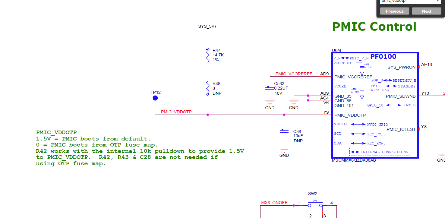
I am looking at the QWKS-SCM-IMX6DQ, Quick Start Board for SCM-i.MX 6DQ, and found on Page 7 PMIC Control block. It says
PMIC_VDDOTP
1.5V = PMIC boots from default.
0 = PMIC boots from OTP fuse map.
R42 works with the internal 10k pulldown to provide 1.5V
to PMIC_VDDOTP. R42, R43 & C28 are not needed if
using OTP fuse map.
This is inconsistent with the schematic. Could you please help clarify this? Thank you very much! Schematic and screen shoot attached.
Jianxin
已解决! 转到解答。
1 解答
04-25-2018
06:52 AM
1,249 次查看
sunjianxin66
Contributor II
Thanks for the reply
Just confirm, are the R42, R43 and C28 mentioned in the green color paragraph should be R47, R48 and C38 in the schematic connection?
Thank you.
Jianxin
3 回复数