- Forums
- Product Forums
- General Purpose MicrocontrollersGeneral Purpose Microcontrollers
- i.MX Forumsi.MX Forums
- QorIQ Processing PlatformsQorIQ Processing Platforms
- Identification and SecurityIdentification and Security
- Power ManagementPower Management
- MCX Microcontrollers
- S32G
- S32K
- S32V
- MPC5xxx
- Other NXP Products
- Wireless Connectivity
- S12 / MagniV Microcontrollers
- Powertrain and Electrification Analog Drivers
- Sensors
- Vybrid Processors
- Digital Signal Controllers
- 8-bit Microcontrollers
- ColdFire/68K Microcontrollers and Processors
- PowerQUICC Processors
- OSBDM and TBDML
- S32M
-
- Solution Forums
- Software Forums
- MCUXpresso Software and ToolsMCUXpresso Software and Tools
- CodeWarriorCodeWarrior
- MQX Software SolutionsMQX Software Solutions
- Model-Based Design Toolbox (MBDT)Model-Based Design Toolbox (MBDT)
- FreeMASTER
- eIQ Machine Learning Software
- Embedded Software and Tools Clinic
- S32 SDK
- S32 Design Studio
- GUI Guider
- Zephyr Project
- Voice Technology
- Application Software Packs
- Secure Provisioning SDK (SPSDK)
- Processor Expert Software
-
- Topics
- Mobile Robotics - Drones and RoversMobile Robotics - Drones and Rovers
- NXP Training ContentNXP Training Content
- University ProgramsUniversity Programs
- Rapid IoT
- NXP Designs
- SafeAssure-Community
- OSS Security & Maintenance
- Using Our Community
-
- Cloud Lab Forums
-
- Knowledge Bases
- ARM Microcontrollers
- i.MX Processors
- Identification and Security
- Model-Based Design Toolbox (MBDT)
- QorIQ Processing Platforms
- S32 Automotive Processing Platform
- Wireless Connectivity
- CodeWarrior
- MCUXpresso Suite of Software and Tools
- MQX Software Solutions
-
Freescale Freedom Board mounting on Freescale Cup car
Freescale Freedom Board mounting on Freescale Cup car
One option for mounting the FRDM-KL25Z Freescale Freedom board to the car chassis.
[no audio]
Important Note: Secure the wires coming from your motors!! (I used a zip tie in the video) If they are allowed to flex at the joint where the wire connects to the motor, it will eventually fail.
I just used foamy double-stick tape on freedom board to so that board could be mounted longwise parallel to main axis of car. Didn't think motor wires would reach unless green ports near back of car.
Will make it hard if I want to replace board but figured it needed to be stable.
What's the red bit that appeared around 4:43? Electrical tape?
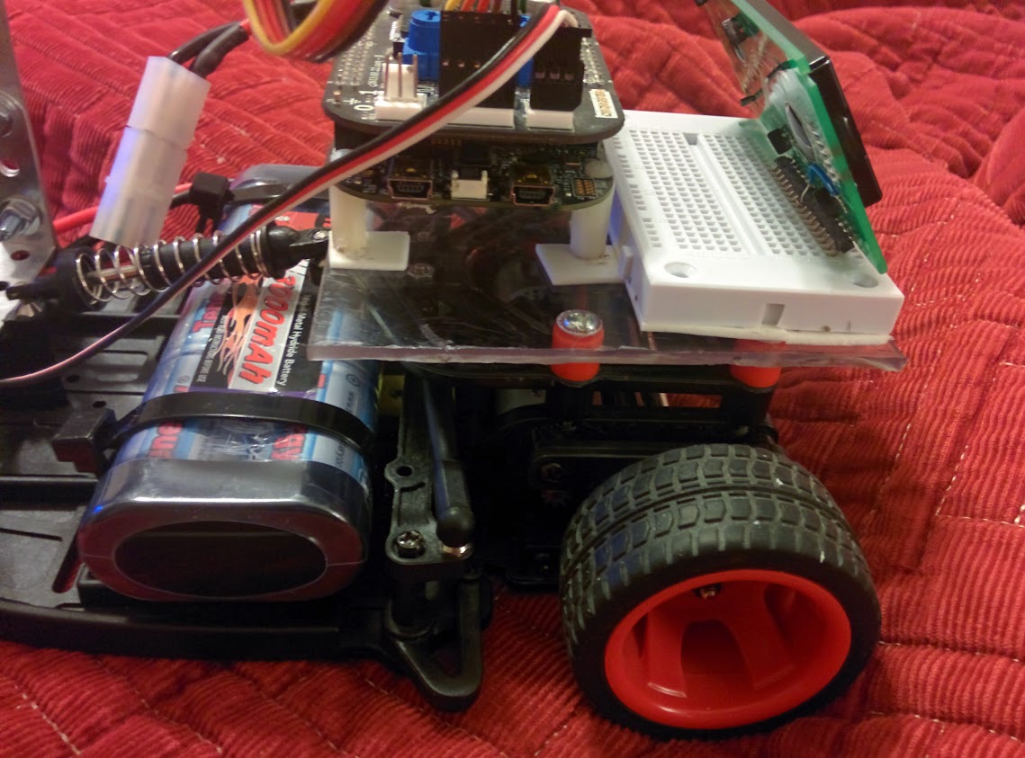
Used acrylic mounted to the 4 screws on top. This permits adding a small breadboard. And can change to something different if desired in the future.
Now the question is how to access extra GPIOs since shield covers them up?? Stackable headers I suppose...

Well darn. Last night attempted to remove the current headers from the shield board and managed to damage some of the tiny traces and one of the regulators. Shouldn't have used the dremel saw :smileyshocked:. Finally figured the best technique for pin header removal on the side where the fewest GPIOs were available!
Will try to work on fixing them-- but might ask local helper Deactivated user for another shield...
Stackable headers seem to be the only way to go to access the extra GPIOs so I can talk to other stuff. Wish the shields came with headers detached so user can decide whether to use stackable!
Ok, talked with dgd, going to fab an interface board to go between the FRDM-TFC and KL25Z boards that will permit easy access to any of the pins from the side. Will be able to be used for any FRDM board.
Something like this: Overview | Adafruit Proto Shield for Arduino | Adafruit Learning System but that allows for going out from the side in case it's sandwiched between 2 other boards. Maybe ultimately could be turned into a tower-type interface.
emh203, do we already have such a board?
I had started on but never finished.
I assume that you wanted an area that shoots out beyond the normal shield boundary for the signal access?
Yep.
I was thinking too we could do something like this: https://oshpark.com/shared_projects/fKTvynYj
But specifically for FRDM Boards--user cuts it apart and only uses the bits they want.
Hmm... ok. Now have another problem. How to get 5V off the FRDM-TFC board. I see 5V is on there to drive the inputs to the H-bridges. Wonder if I can tap off of that to drive my 2x16 LCD (generic HD44870).
Wonder if a "C" TFC board is in the works and whether I or others should have inputs to it?
4 Zip ties! The PCb was design for this orientation.
Well, since I am the one who did Rev B, we could always do a Rev C. We would need some cash to do a proto-run. I would be happy to make the edits. Maybe start a new document with ideas. I do have a few minor changes if a Rev C was ever done.
The question is in the right person to insert it into the production line. John M was the person I worked through before. Is it now Damaris Ochoa Flores?
Eli, I am checking with Damaris and Andy.
Thanks! Yes that is my original orientation-- but the chassis changed now to include a bit of extra screws on it to support the motor leads to keep them secure on the right side now. Those motor secure screws caused a short under one of the boards this past summer so something between KL25Z and chassis was needed. Plus I want to have space to add a prototyping board next to it. Want the LCD facing to the back to make it easy to read while car is going by! Also I have a car whose battery has much shorter leads- making it difficult to reach the very back of the board.
Here is what I mean:
This is a better photo show how the acrylic is attached. The orange spacers are erector set. Having Erector leftovers has proven to be very useful!
A google doc would be a great idea! I have lots of ideas! Need to write them down before I forget...
... althougth as I'm making a list and looking at the shield there really isn't room for more ports. Not unless we removed the "1" ports (speed, camera, servo) ports and used for something else.
Maybe thinking of a way to extend the TFC board somehow might be better. Maybe a go-between board that has the wider ports to permit protyping, connections for additional peripherals etc.
An example would be if the TFC shield had HC-06 compatibility, then could make an Android app that talks to it. That would save room by not having to have pots, buttons, DIP switches, LEDs on the board. It would just have maybe one or two to server to debug the bluetooth (or whatever comm mechanism desired). There would be a virtual control in the app.
That might require a different TFC shield altogether. Maybe a FRDM-TFC-BT ??
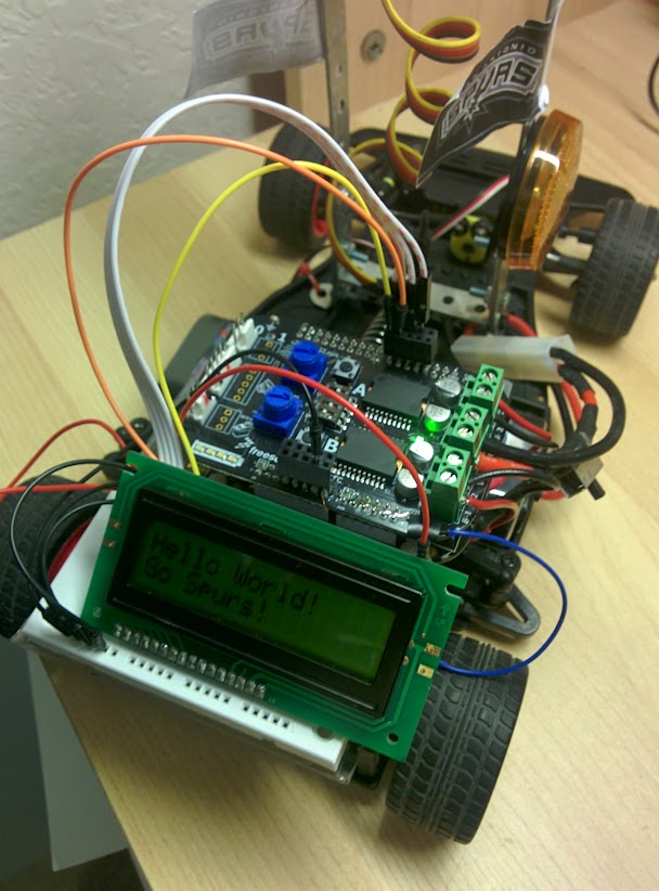
Just had to share! Got the LCD working with the TFC board in place NOT connected to USB.
Currently just running a Hello World mbed project-- but I was able to connect to the 5V off the TFC board (blue wire to the right). BTW, this time just added pin headers right on top of the TFC board without desoldering. So much easier!

>>Now the question is how to access extra GPIOs since shield covers them up?? Stackable headers I suppose...
I just soldered Dupont wires directly to the exposed pins on the shield.
Bob
