
- Forums
- Product Forums
- General Purpose MicrocontrollersGeneral Purpose Microcontrollers
- i.MX Forumsi.MX Forums
- QorIQ Processing PlatformsQorIQ Processing Platforms
- Identification and SecurityIdentification and Security
- Power ManagementPower Management
- Wireless ConnectivityWireless Connectivity
- RFID / NFCRFID / NFC
- Advanced AnalogAdvanced Analog
- Neural Processing UnitsNeural Processing Units
- MCX Microcontrollers
- S32G
- S32K
- S32V
- MPC5xxx
- Other NXP Products
- S12 / MagniV Microcontrollers
- Powertrain and Electrification Analog Drivers
- Sensors
- Vybrid Processors
- Digital Signal Controllers
- 8-bit Microcontrollers
- ColdFire/68K Microcontrollers and Processors
- PowerQUICC Processors
- OSBDM and TBDML
- S32M
- S32Z/E
-
- Solution Forums
- Software Forums
- MCUXpresso Software and ToolsMCUXpresso Software and Tools
- CodeWarriorCodeWarrior
- MQX Software SolutionsMQX Software Solutions
- Model-Based Design Toolbox (MBDT)Model-Based Design Toolbox (MBDT)
- FreeMASTER
- eIQ Machine Learning Software
- Embedded Software and Tools Clinic
- S32 SDK
- S32 Design Studio
- GUI Guider
- Zephyr Project
- Voice Technology
- Application Software Packs
- Secure Provisioning SDK (SPSDK)
- Processor Expert Software
- Generative AI & LLMs
-
- Topics
- Mobile Robotics - Drones and RoversMobile Robotics - Drones and Rovers
- NXP Training ContentNXP Training Content
- University ProgramsUniversity Programs
- Rapid IoT
- NXP Designs
- SafeAssure-Community
- OSS Security & Maintenance
- Using Our Community
-
- Cloud Lab Forums
-
- Knowledge Bases
- ARM Microcontrollers
- i.MX Processors
- Identification and Security
- Model-Based Design Toolbox (MBDT)
- QorIQ Processing Platforms
- S32 Automotive Processing Platform
- Wireless Connectivity
- CodeWarrior
- MCUXpresso Suite of Software and Tools
- MQX Software Solutions
- RFID / NFC
- Advanced Analog
- Neural Processing Units
-
- NXP Tech Blogs
Freescale Cup Shield for the Freedom KL25Z
Freescale Cup Shield for the Freedom KL25Z
Overview
The FRDM-TFC is a convenient "shield" that can drive up to two DC motors (5A per channel), two servos and I/O for the Freescale cup line scan camera and Hall effect sensors. This board mates with the KL25Z Freedom board for primary usage with a Freescale Cup car.
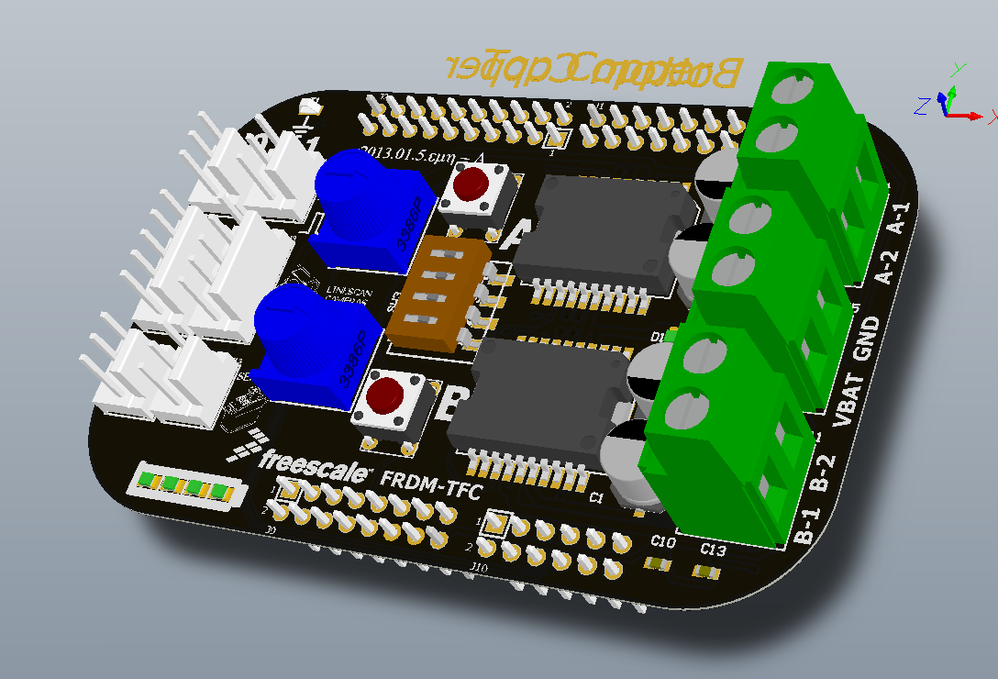
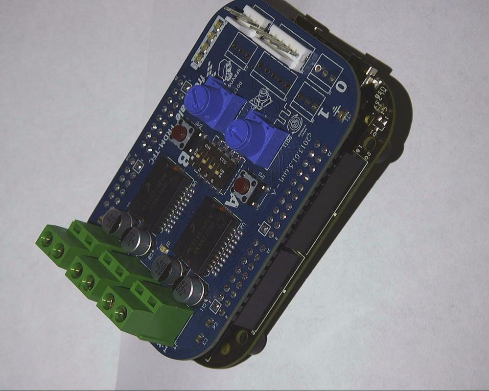
Features:
- 2 channel Motor Driver ICs (MC33887APVW)
- 2 channel servo Outputs
- Dual Linescan Camera interfaces
- Two inputs for speed sensors
- Two potentiometers for user functions
- Two push buttons for user functions
- 4 Position DIP Switch for user function
- 4 LEDs (green) for battery indicator or user functions
Design Files
Rev A is attached to this document.
Rev B is attached to this document
Code Examples
Codewarrior "Bare Metal" Example Code:
All Codewarrior based code examples for the FRDM-TFC are hosted on in a Subversion repository on Google Code:
frdm-tfc - Example code for the FRDM-TFC Shield - Google Project Hosting
You can check out the code with your favorite SVN client. Static releases are available in the attachments section of this page. The current release is "R1.0"
mbed.org Example Code:
https://mbed.org/components/Freescale-Cup-with-FRDM-KL25Z/
Videos
FRDM TFC EXAMPLE CODE GETTING STARTED
FRDM-TFC_DEMO 0 and 1
FRDM-TFC_DEMO 2 and 3

Hi,
thanks for your answers. We tryed to do this changes at the servo but unfortunately the servo doesnt rotates.
Maybe our processorsetup in the KDS or the wireing is not correct.
Can you tell us at the example of the servo what we have to change at the connections and at the code?
I'm sorry but we are very new at microcontrolers.
Thanks,
David

David:
I would suggest you 1st try to get the system working with the KL25Z board. It is a known working configuration with working example code. If you are new to micro controllers, it will save you a lot of time. Once you understand the initialization code for that platform, them move on. Also, if you are using processor expert you may get stuck for awhile. It is better to 1st understand how to program the timer units from scratch using the reference manual so you understand what operations you are doing.
Some resources:
1.) https://community.freescale.com/docs/DOC-95170
2.) Some have used the Kwikstik for the car. It uses a K40 which has the same FTM unit as the K64. That code may be helpful to you.

Hey ,
I have a big problem with mi FRDM KL25Z ...
I have made a lot of test and all were good ! i success to do several thing and now i am friend with the code and code warrior !
So i intent to make my own code to the CUP , using the camera in order to control the car BUT
during the execution of the program all the shiel froze totally ... and the moto are in FULL POWER !! in my code i put the LED blinking and it Froze also !! i have to press the reset button and it is good for some seconde and again it froze in full power ...
I take the time with a chronometer between the beginning and the Froze , and it depend of the number of execution in my loop ... 50 times and Froze !!
explanation : my code is :
main(){
while(1) {
if( ticker[0] > T)
ticker = 0
instruction;
instruction ;
..
..
}
}
So i notice that the car froze in full power when the code do 50 times the " if ticker ..... " .
so it go out of the while after 50*T ... and all the power of the motor a the maximum ...
A dont understand why ???!!! I really need help because in 1 big month there are the qualification EMEAa ...
More over the gears of the motor transmission was broken during the shield froze because of the full power in the motor .. Do you know where i can by a new ?
BEST , thanksss
LUCAS mAHIEU
PS : Sorry i am french and my english is not really good ...
Hello Lucas:
Let's start here... Can you zip your test project where you said the LED was freezing? I need to see the code in the context of your entire project.
Also, what happens when you load the example/test code from this page:
thank a lot, but i fixed the problem ! it was the dynamic allocation the problem … I didn’t made the FREE …
but today a very BIZARRE thing happen … When i plug the FRDM KL25Z to send my program all is good the car do what i want ! , but when i unplug he usb cable the car do nothing … first i thought that it is the batterie , but it is full … and we saw that the board is VERY VERY VERY hot at the bottom !! near to the component with 3 pin in one side an 1 big pin in the other side … today it was the first time that we saw that !!
do you have an idea ?
Le 18 déc. 2014 à 13:56, Eli Hughes <[email protected]> a écrit :
<https://community.freescale.com/> <https://community.freescale.com/>
Freescale Cup Shield for the Freedom KL25Z
new comment by Eli Hughes <https://community.freescale.com/people/eli_hughes?et=watches.email.document_comment> View all comments on this document <https://community.freescale.com/docs/DOC-93914?et=watches.email.document_comment#comment-15266>
Hello Lucas:
Let's start here... Can you zip your test project where you said the LED was freezing? I need to see the code in the context of your entire project.
Also, what happens when you load the example/test code from this page:
https://community.freescale.com/docs/DOC-93914 <https://community.freescale.com/docs/DOC-93914>
Reply to this email to respond to Eli Hughes's comment.
Following Freescale Cup Shield for the Freedom KL25Z <https://community.freescale.com/docs/DOC-93914?et=watches.email.document_comment#comment-15266> in these streams: Inbox
hello,
one of the features of the TFC is the H-bridge IFA\IFB. I ave few things that i didn't understand:
1. what are they use for?
2. they give us the feedback from the H-bridge of the PWM output? if yes, can we use them as speed sensors of the car?
3. is there a way to check the status of the battery with the KL25Z (the voltage of the battery)? if yes, how can we check it.
thank you for this examples!!!
1.) Look in the MC33887APVW datasheet. The are current feedback signals you could use for torque control on the motor.
2.) Yes. Look at the schematic and you will find your answer.
Hello, We participat to the Freeacale cup for the EMEA in 3 weeks.
But we have a big probleme ...
We have made our code on code warrior.
All was corect and the car did what we wanted ...
but suddenly the shield was very HOT and a litte connection burn on the FRDM-TFC !! betwen the pin 16 (J9) and the VBAT ... More over we try again with another shiel and we had the same problem and the R8 resistance burned to ...
So we descided to take an other shiel ( new one ) and we try with a litte and simple program ! juste with the "chemillards". bat led in the main.c of heli huges in the quick start program at the begining all was good...
but after about 4 minutes the connection on the shield burn too ...
We are very disaponted because we don't find the probleme and we realy don't understand why we had not this problem a the begining when the car was eficient ...
thanks before !
all progrmag are running but in a flew time a connection burn ...

Hello Jawahar,
Check the videos for some reference. But you will have to acquire locally in any electronics store a Hall Effect Sensor. I suggest you to research on the Internet how they work. And depending on the package of the sensor, you can create your own case to be able to add it to the wheels on your car.
Regards,
Hi,
I have an issue with the speed sensor. I use the Kinetis FRDM-KL25Z. On the FRDM-TFC there are 3 pins for a speed sensor. But I do not know how to use. I looked at the sample code but there is nothing.
Do you have a code to exploit this sensor.
thank you
The sample code for a speed sensor was intentionally left out. The speed sensor design is up to the student team as an exercise. You will need to design your own and write the code. There are many clues in this video:
See "Designing a Speed Sensor II & II" on this page
The Book of Eli - Microcontrollers, robotics and warp drives
The sample code for a speed sensor was intentionally left out. The speed sensor design is up to the student team as an exercise. You will need to design your own and write the code. There are many clues in this video:
See "Designing a Speed Sensor II & II" on this page
The Book of Eli - Microcontrollers, robotics and warp drives

Hello Mr. Hughes,
How can I manage to handle the SDA, the UART0 and the Speed Sensor on the same ports like wired on the TFC-shield. I have written an c-file and a header file for the speed sensor. My ISR did not start up in case of overflow or reaching the mod. value. Could there be a conflict with the SDA or UART0?
Thanks
MB
If you look at the schematics for the KL25Z and the FRDM_TFC, you will see that the timers used for the speed sense cannot be used if you are also using the UART for the SDA. IT is possible to change the uart function (which some jumper wires) to connect UART2 to the SDA interface. I believe Daniel Hadad did this already. There may be some instructions on the forum, I will look around.
How can I access the i/o ports on the board after attatching the shield to the FRDM-KL25Z ?
1.) Solder leads to the terminals on the shield
2.) Do a web search for an arduino shield that has a pass through connector and some protoyping area.
Hello Mr. Hughes,
for building a connection board between K64F an TFC Shield i need some information about the pin layout of the K64F. Unfortunately I cant find any information on which Pins the PTA10, PTA11, PTB12, PTB13, PTD5, PTD6, PTD7, PTE1 signals are available at the K64F. Can you please give me this information or some advice where it is written?
I also want to know for what the V_Batterie Signal on TFC Pin Jx9 is standing for and if it is necessary to connect this signal with the K64F Board.
Thank you very much,
David
When I turn the exposure time lower then 50 ms I receive some weird noise in the Lab View application that let's me see the signal from the video camera. There are random pikes in the signal that appear rapidly and disappear or the image is unstable is moving very fast up and down like it's "shivering" very fast. Any idea why ? This happens at low exposure time , below 50-45 ms .
Hello,
with my team we would like to create a Rx connection on the car.
In the start package there is the code to the Tx with the UART but not the Rx.
One other words, we can receive information FROM the car but not to give information TO the car.
And the UART fils is VERY VERY difficult to understand for us... is it possible to receive help from somebody ?
Thanks a lot before