- Forums
- Product Forums
- General Purpose MicrocontrollersGeneral Purpose Microcontrollers
- i.MX Forumsi.MX Forums
- QorIQ Processing PlatformsQorIQ Processing Platforms
- Identification and SecurityIdentification and Security
- Power ManagementPower Management
- Wireless ConnectivityWireless Connectivity
- RFID / NFCRFID / NFC
- MCX Microcontrollers
- S32G
- S32K
- S32V
- MPC5xxx
- Other NXP Products
- S12 / MagniV Microcontrollers
- Powertrain and Electrification Analog Drivers
- Sensors
- Vybrid Processors
- Digital Signal Controllers
- 8-bit Microcontrollers
- ColdFire/68K Microcontrollers and Processors
- PowerQUICC Processors
- OSBDM and TBDML
- S32M
-
- Solution Forums
- Software Forums
- MCUXpresso Software and ToolsMCUXpresso Software and Tools
- CodeWarriorCodeWarrior
- MQX Software SolutionsMQX Software Solutions
- Model-Based Design Toolbox (MBDT)Model-Based Design Toolbox (MBDT)
- FreeMASTER
- eIQ Machine Learning Software
- Embedded Software and Tools Clinic
- S32 SDK
- S32 Design Studio
- GUI Guider
- Zephyr Project
- Voice Technology
- Application Software Packs
- Secure Provisioning SDK (SPSDK)
- Processor Expert Software
-
- Topics
- Mobile Robotics - Drones and RoversMobile Robotics - Drones and Rovers
- NXP Training ContentNXP Training Content
- University ProgramsUniversity Programs
- Rapid IoT
- NXP Designs
- SafeAssure-Community
- OSS Security & Maintenance
- Using Our Community
-
- Cloud Lab Forums
-
- Knowledge Bases
- ARM Microcontrollers
- i.MX Processors
- Identification and Security
- Model-Based Design Toolbox (MBDT)
- QorIQ Processing Platforms
- S32 Automotive Processing Platform
- Wireless Connectivity
- CodeWarrior
- MCUXpresso Suite of Software and Tools
- MQX Software Solutions
-
- Home
- :
- Product Forums
- :
- S32K
- :
- Re: PWM showing deviation in the Duty cycle
PWM showing deviation in the Duty cycle
- Subscribe to RSS Feed
- Mark Topic as New
- Mark Topic as Read
- Float this Topic for Current User
- Bookmark
- Subscribe
- Mute
- Printer Friendly Page
- Mark as New
- Bookmark
- Subscribe
- Mute
- Subscribe to RSS Feed
- Permalink
- Report Inappropriate Content
Hi I was working on nxp s32k324 controller . The PWM out put duty cycle showing 2.7 to 3 % difference . when we give the 0x4000 then we are expecting an PWM output with 50% duty cycle but we getting an PWM signal with 53% duty cycle . We are using 160MHz clock and we used the EmiosChPrescaler : EMIOS_PWM_IP_CLOCK_DIV_16 so the resultant clock to the emios is 10MHZ.
we need to run the PWM at 500Hz So we used the PWM period default to 20000 ticks.
And we are also noticed when the frequency is more then the deviation is also more for eg if we are running the pwm at 1khz then the deviation is 6.3% Could you please help as to resolve the issue? Attached the wave forms
Solved! Go to Solution.
- Mark as New
- Bookmark
- Subscribe
- Mute
- Subscribe to RSS Feed
- Permalink
- Report Inappropriate Content
Hello Ajul,
To determin the duty-cycle, we need to have the value of the A register.
Something like this:
In the image you posted, the register is cleared.
Regards,
Daniel
- Mark as New
- Bookmark
- Subscribe
- Mute
- Subscribe to RSS Feed
- Permalink
- Report Inappropriate Content
Hi Daniel
Thank you for the support ,
Regards
Ajul
- Mark as New
- Bookmark
- Subscribe
- Mute
- Subscribe to RSS Feed
- Permalink
- Report Inappropriate Content
- Mark as New
- Bookmark
- Subscribe
- Mute
- Subscribe to RSS Feed
- Permalink
- Report Inappropriate Content
Hello @Ajul,
I just sent you my test project.
Do let me know if you have any question.
Thank you,
Daniel
- Mark as New
- Bookmark
- Subscribe
- Mute
- Subscribe to RSS Feed
- Permalink
- Report Inappropriate Content
Hi Daniel,
If the register is not set, then How We can Get a controlled PWM output? right now Iam facing deviation in the Duty cycle I can control the PWM output. Could you please explain this? How to fix this issue?
Thanks
Ajul
- Mark as New
- Bookmark
- Subscribe
- Mute
- Subscribe to RSS Feed
- Permalink
- Report Inappropriate Content
Can you test it with the Emios_Pwm_Ip_Example_S32K342 RTD example?
Or share your project so that I can test it?
If you don't want to share the project here, you can create a ticket.
Regards,
Daniel
- Mark as New
- Bookmark
- Subscribe
- Mute
- Subscribe to RSS Feed
- Permalink
- Report Inappropriate Content
Hello @Ajul,
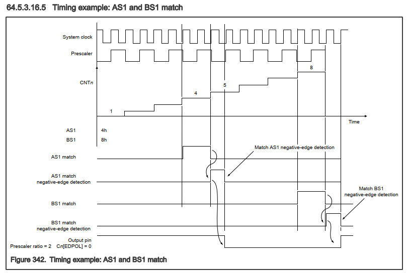
Which EMIOS PWM mode do you use? OPWFMB, OPWMCB, OPWMB, OPWMT?
For example, in the OPWFMB mode, the duty cycle determined by AS1 and the period of BS1.
Can you read the register in with the debugger?
Below is a timing diagram of the expected PWM signal at the output pin.
Thank you,
BR, Daniel
- Mark as New
- Bookmark
- Subscribe
- Mute
- Subscribe to RSS Feed
- Permalink
- Report Inappropriate Content
- Mark as New
- Bookmark
- Subscribe
- Mute
- Subscribe to RSS Feed
- Permalink
- Report Inappropriate Content
Hello Ajul,
I see that the register A is not set.
Was it captured after the initialization while the Emios was running?
Thank you,
BR, Daniel
- Mark as New
- Bookmark
- Subscribe
- Mute
- Subscribe to RSS Feed
- Permalink
- Report Inappropriate Content
Hi Daniel
It is captured during Run time after emios initialization
Regards
Ajul
- Mark as New
- Bookmark
- Subscribe
- Mute
- Subscribe to RSS Feed
- Permalink
- Report Inappropriate Content
Hello Ajul,
To determin the duty-cycle, we need to have the value of the A register.
Something like this:
In the image you posted, the register is cleared.
Regards,
Daniel


