- Forums
- Product Forums
- General Purpose MicrocontrollersGeneral Purpose Microcontrollers
- i.MX Forumsi.MX Forums
- QorIQ Processing PlatformsQorIQ Processing Platforms
- Identification and SecurityIdentification and Security
- Power ManagementPower Management
- Wireless ConnectivityWireless Connectivity
- RFID / NFCRFID / NFC
- Advanced AnalogAdvanced Analog
- MCX Microcontrollers
- S32G
- S32K
- S32V
- MPC5xxx
- Other NXP Products
- S12 / MagniV Microcontrollers
- Powertrain and Electrification Analog Drivers
- Sensors
- Vybrid Processors
- Digital Signal Controllers
- 8-bit Microcontrollers
- ColdFire/68K Microcontrollers and Processors
- PowerQUICC Processors
- OSBDM and TBDML
- S32M
- S32Z/E
-
- Solution Forums
- Software Forums
- MCUXpresso Software and ToolsMCUXpresso Software and Tools
- CodeWarriorCodeWarrior
- MQX Software SolutionsMQX Software Solutions
- Model-Based Design Toolbox (MBDT)Model-Based Design Toolbox (MBDT)
- FreeMASTER
- eIQ Machine Learning Software
- Embedded Software and Tools Clinic
- S32 SDK
- S32 Design Studio
- GUI Guider
- Zephyr Project
- Voice Technology
- Application Software Packs
- Secure Provisioning SDK (SPSDK)
- Processor Expert Software
- Generative AI & LLMs
-
- Topics
- Mobile Robotics - Drones and RoversMobile Robotics - Drones and Rovers
- NXP Training ContentNXP Training Content
- University ProgramsUniversity Programs
- Rapid IoT
- NXP Designs
- SafeAssure-Community
- OSS Security & Maintenance
- Using Our Community
-
- Cloud Lab Forums
-
- Knowledge Bases
- ARM Microcontrollers
- i.MX Processors
- Identification and Security
- Model-Based Design Toolbox (MBDT)
- QorIQ Processing Platforms
- S32 Automotive Processing Platform
- Wireless Connectivity
- CodeWarrior
- MCUXpresso Suite of Software and Tools
- MQX Software Solutions
- RFID / NFC
- Advanced Analog
-
- NXP Tech Blogs
- Home
- :
- RFID / NFC
- :
- NFC
- :
- Matching circuit in the case of differential antenna with twisted pair cable
Matching circuit in the case of differential antenna with twisted pair cable
- RSS フィードを購読する
- トピックを新着としてマーク
- トピックを既読としてマーク
- このトピックを現在のユーザーにフロートします
- ブックマーク
- 購読
- ミュート
- 印刷用ページ
Matching circuit in the case of differential antenna with twisted pair cable
- 新着としてマーク
- ブックマーク
- 購読
- ミュート
- RSS フィードを購読する
- ハイライト
- 印刷
- 不適切なコンテンツを報告
Hello,
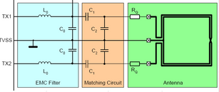
Working on a RFID project that would involve a PN5180 and an external, off pcb, antenna connected with some twisted pair cable (distance is around 1m). Power is not a problem : the system isn't on battery, and the more range the better. I'm using a differential antenna topology and i'm trying to use the "matching antennas.xls" tool provided by NXP. That brings me to the following picture :
Let's say the twisted pair has a characteristic impedance of 50 Ohms and the antenna already has its own matching circuit on the antenna pcb to accomodate for that.
Now, how should i use the excel tool ? Because it seems to adress only the case of antenna next-to the transceiver. How do i need to understand the following sentences taken from the documentation on the PN5180 :
"the antenna impedance is tuned to Z ≈ 20Ω"
and
"Note: The antenna impedance tuning and measurement must be done with R = 10Ω
between ANT1 and ANT2."
(both from AN11744 - page 9/45).
Would there be an advantage to redesign the antenna pcb to change its matching circuit and the type of cable to accomodate for what the PN5180 needs ?
Thank you in advance
- 新着としてマーク
- ブックマーク
- 購読
- ミュート
- RSS フィードを購読する
- ハイライト
- 印刷
- 不適切なコンテンツを報告
Hi @bastiaens,
I also need an external antenna for a reader with PN5180 IC, did you manage to make your reader with the antenna connected by twisted pair? Kindly share any experience.
Best regards,
Osmany
- 新着としてマーク
- ブックマーク
- 購読
- ミュート
- RSS フィードを購読する
- ハイライト
- 印刷
- 不適切なコンテンツを報告
Hello @bastiaens
Thanks for contacting us and say sorry for the late to response.
For your questions, it's recommended that you follow this application notes AN11740 - PN5180 antenna design, which will give you the answers what you want. Please check the attachment.
Please feel free to contact us if any questions.
Best Regards,
kelly
