- Forums
- Product Forums
- General Purpose MicrocontrollersGeneral Purpose Microcontrollers
- i.MX Forumsi.MX Forums
- QorIQ Processing PlatformsQorIQ Processing Platforms
- Identification and SecurityIdentification and Security
- Power ManagementPower Management
- MCX Microcontrollers
- S32G
- S32K
- S32V
- MPC5xxx
- Other NXP Products
- Wireless Connectivity
- S12 / MagniV Microcontrollers
- Powertrain and Electrification Analog Drivers
- Sensors
- Vybrid Processors
- Digital Signal Controllers
- 8-bit Microcontrollers
- ColdFire/68K Microcontrollers and Processors
- PowerQUICC Processors
- OSBDM and TBDML
- S32M
-
- Solution Forums
- Software Forums
- MCUXpresso Software and ToolsMCUXpresso Software and Tools
- CodeWarriorCodeWarrior
- MQX Software SolutionsMQX Software Solutions
- Model-Based Design Toolbox (MBDT)Model-Based Design Toolbox (MBDT)
- FreeMASTER
- eIQ Machine Learning Software
- Embedded Software and Tools Clinic
- S32 SDK
- S32 Design Studio
- GUI Guider
- Zephyr Project
- Voice Technology
- Application Software Packs
- Secure Provisioning SDK (SPSDK)
- Processor Expert Software
- MCUXpresso Training Hub
-
- Topics
- Mobile Robotics - Drones and RoversMobile Robotics - Drones and Rovers
- NXP Training ContentNXP Training Content
- University ProgramsUniversity Programs
- Rapid IoT
- NXP Designs
- SafeAssure-Community
- OSS Security & Maintenance
- Using Our Community
-
- Cloud Lab Forums
-
- Knowledge Bases
- ARM Microcontrollers
- i.MX Processors
- Identification and Security
- Model-Based Design Toolbox (MBDT)
- QorIQ Processing Platforms
- S32 Automotive Processing Platform
- Wireless Connectivity
- CodeWarrior
- MCUXpresso Suite of Software and Tools
- MQX Software Solutions
-
- RSS フィードを購読する
- トピックを新着としてマーク
- トピックを既読としてマーク
- このトピックを現在のユーザーにフロートします
- ブックマーク
- 購読
- ミュート
- 印刷用ページ
MPC5744P Rev. E1 - Code Execution Issue with MBDT or S32
- 新着としてマーク
- ブックマーク
- 購読
- ミュート
- RSS フィードを購読する
- ハイライト
- 印刷
- 不適切なコンテンツを報告
Hi there,
I bought 6 pieces of MPC5744P (Rev. E1) and DEVKIT-COMM (Rev. A) at this year.
I tested different code to verify the functionality of each board, the testing condition is as follow,
【S32 v2.1 / MBDT v3.2 / Matlab R2018a / Windows 10 / ASUS G1401I】
The testing result and question is described as follow.
( to prevent misunderstanding, 6 piece of MPC5744P is numbering as A, B, C, D, E, F )
1.
two out of six board cannot execute the code from MBDT.
I have seen the post discussed the issue of oscillator of clock source, link of post is as below.
MPC5744p RevE MBD flash problem - NXP Community
Therefore, I guess the external clock of two board (A, B) in the above table is malfunction.
If the guess above is true, can I have the return or exchange? @mariuslucianand
2.
four out of four (C, D, E, F) board cannot execute the 【LED & UART】of 【flexcan_master_mpc574x】from MBDT.
*Is the code to initialize the LED not for Rev.E?
(I found this issue from Solved: Re: DEVKIT-MPC5744P CAN testing - NXP Community )
*Is the code to initialize the UART wrong?
@PetrS @mariuslucianand @constantinrazva @raresvasile @adriantudor
If there is any other information needed, please let me know, thanks for your help!
- 新着としてマーク
- ブックマーク
- 購読
- ミュート
- RSS フィードを購読する
- ハイライト
- 印刷
- 不適切なコンテンツを報告
Hi,
I can comment FlexCAN_MPC5744P demo in S32DS.
After doing modification mentioned in Solved: Re: DEVKIT-MPC5744P CAN testing - NXP Community I am able to see terminal message and communicate with CAN tool on rev.E board
No message is send from PC, but receiving on MCU is successful because self reception is enabled MCR[SRXDIS]=0) and RX MB is configured to receive same ID that is send.
Not sure why code for LED control is done that way. But you can easily modify it. Use below code to enable output on PC11
SIUL2.MSCR[PC11].B.OBE = 1; // enable output buffer on PC11, driving red LED
then output level can be controlled by
SIUL2.GPDO[PC11].R = 0; // Turn on red LED
SIUL2.GPDO[PC11].R = 1; // Turn off red LED
SIUL2.GPDO[PC11].R ^= 1; // Toggle red LED
BR, Petr
- 新着としてマーク
- ブックマーク
- 購読
- ミュート
- RSS フィードを購読する
- ハイライト
- 印刷
- 不適切なコンテンツを報告
Hi @PetrS , thanks for your reply and sorry for my delayed response.
I still cannot receive 0x555 from CAN listener ( Komodo CAN Duo ),
but the red led is on.
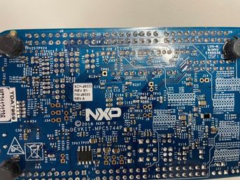
My board version is revE1 as shown in figure below.
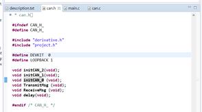
I have modified the code as specified in Solved: Re: DEVKIT-MPC5744P CAN testing - NXP Community as shown in figure below.

My CAN connection is as figure below, CAN0 - CAN2 - CAN listener
However, if I also change the LOOPBACK to 0.
1. the CAN listener can get 0x555
2. the red led is vanished
3. the UART still got nothing
Also, what is the meaning of DS and MB shown in the comment at main.c
By the way, @adriantudor
the UART should print the data received if the description is right as shown in figure below.
However, there is no data shown in UART terminal.
The jumper configuration is shown as figure below and the code is as attached.
Please help me solve these issues, thank you!
- 新着としてマーク
- ブックマーク
- 購読
- ミュート
- RSS フィードを購読する
- ハイライト
- 印刷
- 不適切なコンテンツを報告
Hello @hbhnhbnhj1,
For the second point:
Have you updated the model with the right pin configurations for your board version? If you have done that, please send us your models and a picture with jumpers configurations. As far as I know, the default model "flexcan_master_mpc574x" doesn't use any UART block. Can you send us this model or give us more detail ?
Best regards,
Adrian
- 新着としてマーク
- ブックマーク
- 購読
- ミュート
- RSS フィードを購読する
- ハイライト
- 印刷
- 不適切なコンテンツを報告
Hi @adriantudor,
Thanks for your reply and sorry for my late response.
The feedback is described in the reply to @PetrS,
Re: MPC5744P Rev. E1 - Code Execution Issue with M... - NXP Community
please refer to it, thank you.


