
- Forums
- Product Forums
- General Purpose MicrocontrollersGeneral Purpose Microcontrollers
- i.MX Forumsi.MX Forums
- QorIQ Processing PlatformsQorIQ Processing Platforms
- Identification and SecurityIdentification and Security
- Power ManagementPower Management
- Wireless ConnectivityWireless Connectivity
- RFID / NFCRFID / NFC
- Advanced AnalogAdvanced Analog
- Neural Processing UnitsNeural Processing Units
- MCX Microcontrollers
- S32G
- S32K
- S32V
- MPC5xxx
- Other NXP Products
- S12 / MagniV Microcontrollers
- Powertrain and Electrification Analog Drivers
- Sensors
- Vybrid Processors
- Digital Signal Controllers
- 8-bit Microcontrollers
- ColdFire/68K Microcontrollers and Processors
- PowerQUICC Processors
- OSBDM and TBDML
- S32M
- S32Z/E
-
- Solution Forums
- Software Forums
- MCUXpresso Software and ToolsMCUXpresso Software and Tools
- CodeWarriorCodeWarrior
- MQX Software SolutionsMQX Software Solutions
- Model-Based Design Toolbox (MBDT)Model-Based Design Toolbox (MBDT)
- FreeMASTER
- eIQ Machine Learning Software
- Embedded Software and Tools Clinic
- S32 SDK
- S32 Design Studio
- GUI Guider
- Zephyr Project
- Voice Technology
- Application Software Packs
- Secure Provisioning SDK (SPSDK)
- Processor Expert Software
- Generative AI & LLMs
-
- Topics
- Mobile Robotics - Drones and RoversMobile Robotics - Drones and Rovers
- NXP Training ContentNXP Training Content
- University ProgramsUniversity Programs
- Rapid IoT
- NXP Designs
- SafeAssure-Community
- OSS Security & Maintenance
- Using Our Community
-
- Cloud Lab Forums
-
- Knowledge Bases
- ARM Microcontrollers
- i.MX Processors
- Identification and Security
- Model-Based Design Toolbox (MBDT)
- QorIQ Processing Platforms
- S32 Automotive Processing Platform
- Wireless Connectivity
- CodeWarrior
- MCUXpresso Suite of Software and Tools
- MQX Software Solutions
- RFID / NFC
- Advanced Analog
- Neural Processing Units
-
- NXP Tech Blogs
- Home
- :
- General Purpose Microcontrollers
- :
- LPC Microcontrollers
- :
- LPC1768 problem with ISP
LPC1768 problem with ISP
- Subscribe to RSS Feed
- Mark Topic as New
- Mark Topic as Read
- Float this Topic for Current User
- Bookmark
- Subscribe
- Mute
- Printer Friendly Page
LPC1768 problem with ISP
- Mark as New
- Bookmark
- Subscribe
- Mute
- Subscribe to RSS Feed
- Permalink
- Report Inappropriate Content
Hi everyone,
I'm posting here because I have a problem while flashing a firmware for the first time on a LPC1768 (LQFP100), using a NXPFlasher tool.
The electronical design of the ISP connector and the toolchain I'm using have already functionned on various boards with the same pinout :
RESET to the RESET pin
ISP_RX to P0_3 (UART0)
ISP_TX to P0_2 (UART0)
ISP_BOOT to P2_12 and P2_10 (those two pins are pulled up with a 10k resistor)
When flashing the firmware, I observe on the oscilloscope that both the RESET and the BOOT signal go LOW at the same time, which is supposed to start the ISP command handler, according to the datasheet (page 17). So we already know that the problem isn't linked to the pull up resistors.
I have attached a picture of those signals when flashing the firmware (RESET and BOOT.jpg).
I then tried to observe what happens on the RX and TX pins during flashing, and I have attached two picture with ISP_RX in Yellow and ISP_TX in Blue :
- ISP_RX and ISP_TX normal_function.jpg : On a previously flashed MCU, we see that after two pulses, the TX pin transmits data.
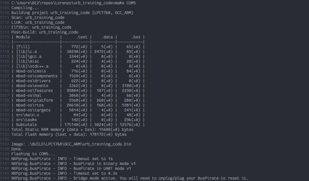
- ISP_RX and ISP_TX malfunction.jpg : On a MCU never flashed before, we see the two initial pulses, but then nothing. I have attached a picture of the output of my terminal : Terminal.png. (Nothing is displayed after the line 5144)
I've spent hours trying to understand what the problem is, if anyone has a clue on what the problem could be I'm all ears.
Please ask me if you need additional infos/screeshots to understand the problem.
Thank you all,
Lorenzo
- Mark as New
- Bookmark
- Subscribe
- Mute
- Subscribe to RSS Feed
- Permalink
- Report Inappropriate Content
Hi,
Thanks for you answer.
After a few hours of looking through everything on the board, I finnaly found the problem : there was a contact failure on one of the 3V3 pins... Such a lame mistake ! Sorry for the long post !
Have a nice day,
Lorenzo
Edit : Also, the pinning was alright, but the names I used are a bit confusing, I agree
- Mark as New
- Bookmark
- Subscribe
- Mute
- Subscribe to RSS Feed
- Permalink
- Report Inappropriate Content
Thank you for your interest in NXP Semiconductor products and
for the opportunity to serve you.
According to your description, the ISP_RX and ISP_TX normal_function.jpg demonstrate the process that the host transmits the image to the LPC1768, so I'd like highly recommend you to use a logic analyzer to parse the data that the ISP_TX transmits, it consists of a variety of ISP commands. Definitely, you can gain an insight into the problem via using the logic analyzer to parse the ISP_RX and ISP_TX malfunction.jpg.
In further, I have two inquiry about ISP connector, maybe need you to clarify them.
1. The ISP_TX transmit data to MCU, in my opinion, the data should be received by the UART_RXD pin, in another word, the ISP_TX should connect the P0_3 pin.
2. Force the LPC1768 to enter the ISP mode, it's nothing with the P2_12.
Have a great day,
TIC
-------------------------------------------------------------------------------
Note:
- If this post answers your question, please click the "Mark Correct" button. Thank you!
- We are following threads for 7 weeks after the last post, later replies are ignored
Please open a new thread and refer to the closed one, if you have a related question at a later point in time.
-------------------------------------------------------------------------------