
- Forums
- Product Forums
- General Purpose MicrocontrollersGeneral Purpose Microcontrollers
- i.MX Forumsi.MX Forums
- QorIQ Processing PlatformsQorIQ Processing Platforms
- Identification and SecurityIdentification and Security
- Power ManagementPower Management
- MCX Microcontrollers
- S32G
- S32K
- S32V
- MPC5xxx
- Other NXP Products
- Wireless Connectivity
- S12 / MagniV Microcontrollers
- Powertrain and Electrification Analog Drivers
- Sensors
- Vybrid Processors
- Digital Signal Controllers
- 8-bit Microcontrollers
- ColdFire/68K Microcontrollers and Processors
- PowerQUICC Processors
- OSBDM and TBDML
-
- Solution Forums
- Software Forums
- MCUXpresso Software and ToolsMCUXpresso Software and Tools
- CodeWarriorCodeWarrior
- MQX Software SolutionsMQX Software Solutions
- Model-Based Design Toolbox (MBDT)Model-Based Design Toolbox (MBDT)
- FreeMASTER
- eIQ Machine Learning Software
- Embedded Software and Tools Clinic
- S32 SDK
- S32 Design Studio
- GUI Guider
- Zephyr Project
- Voice Technology
- Application Software Packs
- Secure Provisioning SDK (SPSDK)
- Processor Expert Software
- MCUXpresso Training Hub
-
- Topics
- Mobile Robotics - Drones and RoversMobile Robotics - Drones and Rovers
- NXP Training ContentNXP Training Content
- University ProgramsUniversity Programs
- Rapid IoT
- NXP Designs
- SafeAssure-Community
- OSS Security & Maintenance
- Using Our Community
-
- Cloud Lab Forums
-
- Knowledge Bases
- ARM Microcontrollers
- i.MX Processors
- Identification and Security
- Model-Based Design Toolbox (MBDT)
- QorIQ Processing Platforms
- S32 Automotive Processing Platform
- Wireless Connectivity
- CodeWarrior
- MCUXpresso Suite of Software and Tools
- MQX Software Solutions
-
- Home
- :
- i.MX Forums
- :
- i.MX Processors
- :
- How can we vary duty cycle on PWM2 for IMX6SL to drive W2812B RGB Strip
How can we vary duty cycle on PWM2 for IMX6SL to drive W2812B RGB Strip
- Subscribe to RSS Feed
- Mark Topic as New
- Mark Topic as Read
- Float this Topic for Current User
- Bookmark
- Subscribe
- Mute
- Printer Friendly Page
How can we vary duty cycle on PWM2 for IMX6SL to drive W2812B RGB Strip
- Mark as New
- Bookmark
- Subscribe
- Mute
- Subscribe to RSS Feed
- Permalink
- Report Inappropriate Content
Hi NXP experts,
I have a task to drive W2812B RGB Strip using PWM2 IMX6SL board. For this strip, the strict timing needs to be followed.
As per strip internals, we need to produce 800Khz on PWM out, for this, we calculated period to be 1250ns.
I made correct entries to DTB like this:-
backlight {
compatible = "pwm-backlight"
pwms = <&pwm2 0 1250>
brightness-levels = <0 74 163 255>;
default-brightness-levels = <0>;
}
&pwm2 {
status = "okay"
}
pwm2 {
pinctrl_harman_iot_pwm2 : pwm2-fornt-led {
fsl,pins = <MX6SL_PAD_EPDC_SDCE3__PWM2_OUT 0x110b0>
}
}
When kernel boots up, LED strip remains off, as default-level is 0.
First, when we do echo 1 > /sys/class/backlight/backlight/brightness, we see PWMSAR register written with 362, i believe this is the first sample value for FIFO. We see correct duty as 33%
Then, we do echo 2 > /sys/class/backlight/backlight/brightness, we see PWMSAR register written with 163 and we see correct duty as 66%
Now, the question is
1. How can we get variable duty cycle in single pulse? Because, driver gets set to the particular duty cycle and starts running pulse of that duty (infinitely). Even if we send echo multiple times, with correct different values, PWM IMX only works on last PWM SAR duty cycle?
2. How can we modify both these values ? Do we need to change these values at all for producing multiple duty cycle?
* Prescale is always coming as 1
* period_cycles = 82 - 2 = 80
As per LED datasheet,
1. we need 800ns as 1 and rest 450ns as 0 - so that LED takes this as 1
2. we need 450 ns as 1 and rest 800ns as 0 - so that LED takes this as 0
3. for reset, we need 5000ns delay - which can be sent as 0.
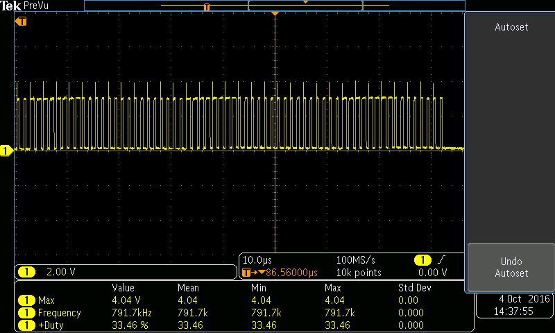
3. We need to actually drive red,green,blue color using this LED strip, and we need to achieve this waveform, which i have attached it is for red color for RPI2. How can we acheive this waveform using PWM-IMX driver?
Is it achievable? Please refer to tek0000.png file for waveform.
4. How can we achieve this waveform, what settings we should do, and how we should send data to PWM SAR config register each time is our concern?
5. Do we need to change clock i.e 66 MHz which we are using, currently, we are giving HIGH_IPG clock?
Kindly help in achieving this task?
Regards
Sudhanshu
- Mark as New
- Bookmark
- Subscribe
- Mute
- Subscribe to RSS Feed
- Permalink
- Report Inappropriate Content
Yes, i took help from bare-metal sdk examples to vary duty-cycle. Its working now.
Thanks a ton!
- Mark as New
- Bookmark
- Subscribe
- Mute
- Subscribe to RSS Feed
- Permalink
- Report Inappropriate Content
Hi Sudhanshu
please check pwm changing duty cycle link
i.MX53 (also i.MX6) PWM Glitches on Duty Cycle Change
it may be useful to check code changes with attached sdk pwm
baremetal test and description in pdf file Chapter 27 Configuring the PWM driver
Best regards
igor
-----------------------------------------------------------------------------------------------------------------------
Note: If this post answers your question, please click the Correct Answer button. Thank you!
-----------------------------------------------------------------------------------------------------------------------
- Mark as New
- Bookmark
- Subscribe
- Mute
- Subscribe to RSS Feed
- Permalink
- Report Inappropriate Content
Hi igor,
Thanks for your reply.
How can we use this SDK PWM source code?
I am newbie to IMX6SL reference boards, and not sure what all is needed to make this program compile for my IMX6SL board. I have arm cross compiler setup on my yocto machine.
Please let me know where can i get all necessary header files to make this PWM program run:
#include "interrupt.h"
#include "iomux_config.h"
#include "registers/regspwm.h"
??
Regards
Sudhanshu
- Mark as New
- Bookmark
- Subscribe
- Mute
- Subscribe to RSS Feed
- Permalink
- Report Inappropriate Content
Hi igor,
Can you please help in getting required bare-metal pwm driver code to run on our IMX6SL custom board?
How can we use this SDK PWM source code?
I am newbie to IMX6SL reference boards, and not sure what all is needed to make this program compile for my IMX6SL board. I have arm cross compiler setup on my yocto machine.
Please let me know where can i get all necessary header files to make this PWM program run:
#include "interrupt.h"
#include "iomux_config.h"
#include "registers/regspwm.h"
Regards
Sudhanshu
- Mark as New
- Bookmark
- Subscribe
- Mute
- Subscribe to RSS Feed
- Permalink
- Report Inappropriate Content
Hi Sudhanshu
one can check
https://community.freescale.com/docs/DOC-103736
for obtaining headers one can create service request
and get full sdk package .
Best regards
igor