
- Forums
- Product Forums
- General Purpose MicrocontrollersGeneral Purpose Microcontrollers
- i.MX Forumsi.MX Forums
- QorIQ Processing PlatformsQorIQ Processing Platforms
- Identification and SecurityIdentification and Security
- Power ManagementPower Management
- Wireless ConnectivityWireless Connectivity
- RFID / NFCRFID / NFC
- Advanced AnalogAdvanced Analog
- Neural Processing UnitsNeural Processing Units
- MCX Microcontrollers
- S32G
- S32K
- S32V
- MPC5xxx
- Other NXP Products
- S12 / MagniV Microcontrollers
- Powertrain and Electrification Analog Drivers
- Sensors
- Vybrid Processors
- Digital Signal Controllers
- 8-bit Microcontrollers
- ColdFire/68K Microcontrollers and Processors
- PowerQUICC Processors
- OSBDM and TBDML
- S32M
- S32Z/E
-
- Solution Forums
- Software Forums
- MCUXpresso Software and ToolsMCUXpresso Software and Tools
- CodeWarriorCodeWarrior
- MQX Software SolutionsMQX Software Solutions
- Model-Based Design Toolbox (MBDT)Model-Based Design Toolbox (MBDT)
- FreeMASTER
- eIQ Machine Learning Software
- Embedded Software and Tools Clinic
- S32 SDK
- S32 Design Studio
- GUI Guider
- Zephyr Project
- Voice Technology
- Application Software Packs
- Secure Provisioning SDK (SPSDK)
- Processor Expert Software
- Generative AI & LLMs
-
- Topics
- Mobile Robotics - Drones and RoversMobile Robotics - Drones and Rovers
- NXP Training ContentNXP Training Content
- University ProgramsUniversity Programs
- Rapid IoT
- NXP Designs
- SafeAssure-Community
- OSS Security & Maintenance
- Using Our Community
-
- Cloud Lab Forums
-
- Knowledge Bases
- ARM Microcontrollers
- i.MX Processors
- Identification and Security
- Model-Based Design Toolbox (MBDT)
- QorIQ Processing Platforms
- S32 Automotive Processing Platform
- Wireless Connectivity
- CodeWarrior
- MCUXpresso Suite of Software and Tools
- MQX Software Solutions
- RFID / NFC
- Advanced Analog
- Neural Processing Units
-
- NXP Tech Blogs
- Home
- :
- Product Forums
- :
- Sensors
- :
- Re: Problem communicating with MMA8452Q
Problem communicating with MMA8452Q
- Subscribe to RSS Feed
- Mark Topic as New
- Mark Topic as Read
- Float this Topic for Current User
- Bookmark
- Subscribe
- Mute
- Printer Friendly Page
As of February 2, 2026, the NXP MEMS Sensor products have been transferred to STMicroelectronics. For details on the transferred products, see this page. Please reach out to STMicroelectronics for further information.
- Mark as New
- Bookmark
- Subscribe
- Mute
- Subscribe to RSS Feed
- Permalink
- Report Inappropriate Content
Hi! I'm having problems with this accelerometer. I'm using an FRDM KL25Z and I tested the onboard MMA8451Q with this code:
MMA8451Q - Bare metal example project
This code works great. The problem started when I wanted to try this code with the MMA8452Q. I modified the code so I can use it with the I2C1 module and I used PTC1 as SCL and PTC2 as SDA. Also, I used PTA5 for the interrupt. So, the configuration is like this:
/******************************************************************************
* MCU initialization function
******************************************************************************/
void MCU_Init(void)
{
//I2C0 module initialization
SIM_SCGC4 |= SIM_SCGC4_I2C1_MASK; // Turn on clock to I2C0 module
SIM_SCGC5 |= SIM_SCGC5_PORTC_MASK; // Turn on clock to Port C module
PORTC_PCR1 = PORT_PCR_MUX(2); // PTC1 pin is I2C1 SCL line
PORTC_PCR2 = PORT_PCR_MUX(2); // PTC2 pin is I2C1 SDA line
I2C1_F = 0x14; // SDA hold time = 2.125us, SCL start hold time = 4.25us, SCL stop hold time = 5.125us *
I2C1_C1 = I2C_C1_IICEN_MASK; // Enable I2C0 module
//Configure the PTA5 pin (connected to the INT1 of the MMA8451Q) for falling edge interrupts
SIM_SCGC5 |= SIM_SCGC5_PORTA_MASK; // Turn on clock to Port A module
PORTA_PCR5 |= (0|PORT_PCR_ISF_MASK| // Clear the interrupt flag
PORT_PCR_MUX(0x1)| // PTA5 is configured as GPIO
PORT_PCR_IRQC(0xA)); // PTA5 is configured for falling edge interrupts
//Enable PORTA interrupt on NVIC
NVIC_ICPR |= 1 << ((INT_PORTA - 16)%32);
NVIC_ISER |= 1 << ((INT_PORTA - 16)%32);
}
But this doesn't work. The program get stuck in the function I2C_Wait();
If I try to read the WHO AM I register, it always return 0xFF. I tried with two different accelerometers, and both fails.
I attach the complete code, maybe someone can test it.
PD: This is the breakout board that I'm using.
MMA8452 3-Axial Triaxial Digital Accelerometer Module for Arduino - Free Shipping - DealExtreme
Original Attachment has been moved to: MMA8452q_KL25.zip
Solved! Go to Solution.
- Mark as New
- Bookmark
- Subscribe
- Mute
- Subscribe to RSS Feed
- Permalink
- Report Inappropriate Content
Hi Juan,
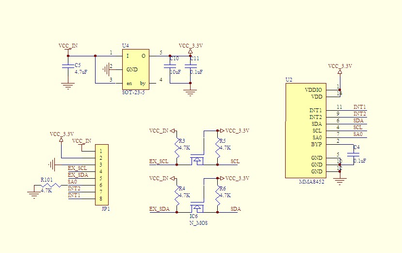
How exactly are you interfacing a 3.3V MKL25Z128VLK4 MCU on the FRDM-KL25Z board with the breakout board? Looking at the schematic, they do not seem to be compatible. There is an on-board 3.3V regulator and MOSFET-based level shifters to interface the breakout board easily with 5V (Arduino) boards only.
Regards,
Tomas
- Mark as New
- Bookmark
- Subscribe
- Mute
- Subscribe to RSS Feed
- Permalink
- Report Inappropriate Content
Hi Juan,
Your source code seems to be properly modified to make use of the I2C1 module (PTC1 and PTC2 pins) and the PTA5 pin. You have also correctly adapted both the I2C.c and I2C.h files.
Is there a schematic of the breakout board you are using available? I was not able to find it. Please double check how is the SA0 pin connected and if necessary change the 7-bit I2C slave address accordingly. Also make sure the INT1 pin is connected properly.
I would also recommend to use a logic analyzer to know what is going on on the I2C bus.
Regards,
Tomas
- Mark as New
- Bookmark
- Subscribe
- Mute
- Subscribe to RSS Feed
- Permalink
- Report Inappropriate Content
I have attached the schematic.
I tried with the SA0 pin to GND and also to 3.3V (and changed the code accordingly), but it's the same, also I checked the INT1 pin connection.
I don't have a logic analyzer, but I have access to an oscilloscope. I'm going to try this, and I will let you know.
Thank you very much for the answer.
- Mark as New
- Bookmark
- Subscribe
- Mute
- Subscribe to RSS Feed
- Permalink
- Report Inappropriate Content
Hi Juan,
How exactly are you interfacing a 3.3V MKL25Z128VLK4 MCU on the FRDM-KL25Z board with the breakout board? Looking at the schematic, they do not seem to be compatible. There is an on-board 3.3V regulator and MOSFET-based level shifters to interface the breakout board easily with 5V (Arduino) boards only.
Regards,
Tomas
- Mark as New
- Bookmark
- Subscribe
- Mute
- Subscribe to RSS Feed
- Permalink
- Report Inappropriate Content
Well... I must be blind, I didn't see the level shifters! I adapted the code now to a JM128 Coldfire V1 running at 5V, and now it works great!
One more question, I was reading AN4069 and I noticed that I have to change the calibration routine in order for it to work correctly with the mma8452 in 2g mode and 12 bits. But this isn't very clear to me.
/******************************************************************************
* Simple offset calibration
******************************************************************************/
void Calibrate (void)
{
unsigned char reg_val = 0;
while (!reg_val) // Wait for a first set of data
{
reg_val = I2C_ReadRegister(MMA845x_I2C_ADDRESS, STATUS_REG) & 0x08;
}
I2C_ReadMultiRegisters(MMA845x_I2C_ADDRESS, OUT_X_MSB_REG, 6, AccData); // Read data output registers 0x01-0x06
Xout_14_bit = ((short) (AccData[0]<<8 | AccData[1])) >> 2; // Compute 14-bit X-axis output value
Yout_14_bit = ((short) (AccData[2]<<8 | AccData[3])) >> 2; // Compute 14-bit Y-axis output value
Zout_14_bit = ((short) (AccData[4]<<8 | AccData[5])) >> 2; // Compute 14-bit Z-axis output value
Xoffset = Xout_14_bit / 8 * (-1); // Compute X-axis offset correction value
Yoffset = Yout_14_bit / 8 * (-1); // Compute Y-axis offset correction value
Zoffset = (Zout_14_bit - SENSITIVITY_2G) / 8 * (-1); // Compute Z-axis offset correction value
I2C_WriteRegister(MMA845x_I2C_ADDRESS, CTRL_REG1, 0x00); // Standby mode to allow writing to the offset registers
I2C_WriteRegister(MMA845x_I2C_ADDRESS, OFF_X_REG, Xoffset);
I2C_WriteRegister(MMA845x_I2C_ADDRESS, OFF_Y_REG, Yoffset);
I2C_WriteRegister(MMA845x_I2C_ADDRESS, OFF_Z_REG, Zoffset);
I2C_WriteRegister(MMA845x_I2C_ADDRESS, CTRL_REG3, 0x00); // Push-pull, active low interrupt
I2C_WriteRegister(MMA845x_I2C_ADDRESS, CTRL_REG4, 0x01); // Enable DRDY interrupt
I2C_WriteRegister(MMA845x_I2C_ADDRESS, CTRL_REG5, 0x01); // DRDY interrupt routed to INT1 - PTA14
I2C_WriteRegister(MMA845x_I2C_ADDRESS, CTRL_REG1, 0x3D); // ODR = 1.56Hz, Reduced noise, Active mode
}
I have made the following changes (marked in bold):
Xout_12_bit = ((short) (AccData[0]<<8 | AccData[1])) >> 4; // Compute 12-bit X-axis output value
Yout_12_bit = ((short) (AccData[2]<<8 | AccData[3])) >> 4; // Compute 12-bit Y-axis output value
Zout_12_bit = ((short) (AccData[4]<<8 | AccData[5])) >> 4; // Compute 12-bit Z-axis output value
Xoffset = Xout_12_bit / 2 * (-1); // Compute X-axis offset correction value
Yoffset = Yout_12_bit / 2 * (-1); // Compute Y-axis offset correction value
Zoffset = (Zout_12_bit - SENSITIVITY_2G) / 2 * (-1); // Compute Z-axis offset correction value
Can you please tell me if this changes are correct?
Thanks, and sorry for the troubles.
- Mark as New
- Bookmark
- Subscribe
- Mute
- Subscribe to RSS Feed
- Permalink
- Report Inappropriate Content
Hi Juan,
Glad to hear that you have got it working with the JM128.
The changes you made are correct. The resolution of all three offset registers (0x2F – 0x31) is ~2mg (1.953125mg) per LSB, so if calibration is done in the ±2g mode (0.9765625mg/count), the 12-bit output data needs to be divided by 2 and then multiplied by -1 to shift the offset to zero. If you calibrated in the ±4g mode (1.953125mg/count), then all you would have to do is multiply the 12-bit output data by -1. In the ±8g mode (3.90625mg/count), the 12-bit output data needs to be multiplied by 2 and -1.
I hope it makes sense. If you have any other questions, just let me know.
Regards,
Tomas
- Mark as New
- Bookmark
- Subscribe
- Mute
- Subscribe to RSS Feed
- Permalink
- Report Inappropriate Content
Thank you very much! You have been very helpfull.