- NXP Forums
- Product Forums
- General Purpose MicrocontrollersGeneral Purpose Microcontrollers
- i.MX Forumsi.MX Forums
- QorIQ Processing PlatformsQorIQ Processing Platforms
- Identification and SecurityIdentification and Security
- Power ManagementPower Management
- MCX Microcontrollers
- S32G
- S32K
- S32V
- MPC5xxx
- Other NXP Products
- Wireless Connectivity
- S12 / MagniV Microcontrollers
- Powertrain and Electrification Analog Drivers
- Sensors
- Vybrid Processors
- Digital Signal Controllers
- 8-bit Microcontrollers
- ColdFire/68K Microcontrollers and Processors
- PowerQUICC Processors
- OSBDM and TBDML
-
- Solution Forums
- Software Forums
- MCUXpresso Software and ToolsMCUXpresso Software and Tools
- CodeWarriorCodeWarrior
- MQX Software SolutionsMQX Software Solutions
- Model-Based Design Toolbox (MBDT)Model-Based Design Toolbox (MBDT)
- FreeMASTER
- eIQ Machine Learning Software
- Embedded Software and Tools Clinic
- S32 SDK
- S32 Design Studio
- GUI Guider
- Zephyr Project
- Voice Technology
- Application Software Packs
- Secure Provisioning SDK (SPSDK)
- Processor Expert Software
-
- Topics
- Mobile Robotics - Drones and RoversMobile Robotics - Drones and Rovers
- NXP Training ContentNXP Training Content
- University ProgramsUniversity Programs
- Rapid IoT
- NXP Designs
- SafeAssure-Community
- OSS Security & Maintenance
- Using Our Community
-
- Cloud Lab Forums
-
S32K312 CAN not working Normal mode
Hello, I'm using the tja1055 as a transceiver. I'm facilitating two-way communication (meaning there's a receiver and a transmitter). I'm using the s32k312 as the processor. As a trial, I have a test code for receiving and transmitting in loopback mode. When I test this code, it works seamlessly. However, in normal mode, I'm not receiving the 'Receive callback.' I can see the signal of the message I send on the RX pin of the receiver transceiver. My message-sending code is a modified version of my loopback code, and my receiver code is the same code with the sending part turned off
Hello rexoplans,i am using s32k312 and configured CAN, are your interrupts configured correctly?, and it should be initialized to work the call_back functions properly, and do you have terminating resistor between the CAN low and CAN high pins?
1. Have you configured and initialized the pins correctly?
2. If everything is configured correctly, then you can use tools such as an oscilloscope or logic analyzer to test whether the TX output on the MCU side has the correct output.
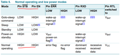
3. If the TX on the MCU side is normal, then solve the problem of TJA1055. Usually the STB and EN pins should be controlled by the MCU side.
Input requirements for STB and EN pins
.pinPortIdx = 6U;
.mux = PORT_MUX_AS_GPIO;
driveStrength = PORT_DRIVE_STRENTGTH_NOT_AVAILABLE;
.inputBuffer = PORT_INPUT_BUFFER_ENABLED;
.outputBuffer = PORT_OUTPUT_BUFFER_DISABLED;
.base = IP_SIUL2;
.safeMode = PORT_SAFE_MODE_DISABLED;
.inputFilter = PORT_INPUT_FILTER_NOT_AVAILABLE;
.pullConfig = PORT_INTERNAL_PULL_NOT_ENABLED;
.slewRateCtrlSel = PORT_SLEW_RATE_NOT_AVAILABLE;
.pullKeep = PORT_PULL_KEEP_DISABLED;
.invert = PORT_INVERT_DISABLED;
.adcInterleaves[0U] = MUX_MODE_NOT_AVAILABLE;
.adcInterleaves[1U] = MUX_MODE_NOT_AVAILABLE;
.initValue = 2U;
.inputMuxReg[0U] = 0U;
.inputMux[0U] = PORT_MUX_ALT4;


