
- Forums
- Product Forums
- General Purpose MicrocontrollersGeneral Purpose Microcontrollers
- i.MX Forumsi.MX Forums
- QorIQ Processing PlatformsQorIQ Processing Platforms
- Identification and SecurityIdentification and Security
- Power ManagementPower Management
- Wireless ConnectivityWireless Connectivity
- RFID / NFCRFID / NFC
- Advanced AnalogAdvanced Analog
- Neural Processing UnitsNeural Processing Units
- MCX Microcontrollers
- S32G
- S32K
- S32V
- MPC5xxx
- Other NXP Products
- S12 / MagniV Microcontrollers
- Powertrain and Electrification Analog Drivers
- Sensors
- Vybrid Processors
- Digital Signal Controllers
- 8-bit Microcontrollers
- ColdFire/68K Microcontrollers and Processors
- PowerQUICC Processors
- OSBDM and TBDML
- S32M
- S32Z/E
-
- Solution Forums
- Software Forums
- MCUXpresso Software and ToolsMCUXpresso Software and Tools
- CodeWarriorCodeWarrior
- MQX Software SolutionsMQX Software Solutions
- Model-Based Design Toolbox (MBDT)Model-Based Design Toolbox (MBDT)
- FreeMASTER
- eIQ Machine Learning Software
- Embedded Software and Tools Clinic
- S32 SDK
- S32 Design Studio
- GUI Guider
- Zephyr Project
- Voice Technology
- Application Software Packs
- Secure Provisioning SDK (SPSDK)
- Processor Expert Software
- Generative AI & LLMs
-
- Topics
- Mobile Robotics - Drones and RoversMobile Robotics - Drones and Rovers
- NXP Training ContentNXP Training Content
- University ProgramsUniversity Programs
- Rapid IoT
- NXP Designs
- SafeAssure-Community
- OSS Security & Maintenance
- Using Our Community
-
- Cloud Lab Forums
-
- Knowledge Bases
- ARM Microcontrollers
- i.MX Processors
- Identification and Security
- Model-Based Design Toolbox (MBDT)
- QorIQ Processing Platforms
- S32 Automotive Processing Platform
- Wireless Connectivity
- CodeWarrior
- MCUXpresso Suite of Software and Tools
- MQX Software Solutions
- RFID / NFC
- Advanced Analog
- Neural Processing Units
-
- NXP Tech Blogs
- Home
- :
- 製品フォーラム
- :
- S12 / MagniVマイクロコントローラ
- :
- S12 XEP100 Clock Speed Math
S12 XEP100 Clock Speed Math
- RSS フィードを購読する
- トピックを新着としてマーク
- トピックを既読としてマーク
- このトピックを現在のユーザーにフロートします
- ブックマーク
- 購読
- ミュート
- 印刷用ページ
- 新着としてマーク
- ブックマーク
- 購読
- ミュート
- RSS フィードを購読する
- ハイライト
- 印刷
- 不適切なコンテンツを報告
Hello,
My company is using an S12 XEP100 General Purpose Eval Board (S12XE General Purpose Evaluation Board | NXP Semiconductors). We have increased the clock speed by turning on the PLL and adjusting the respective register settings. Our settings are as follows:
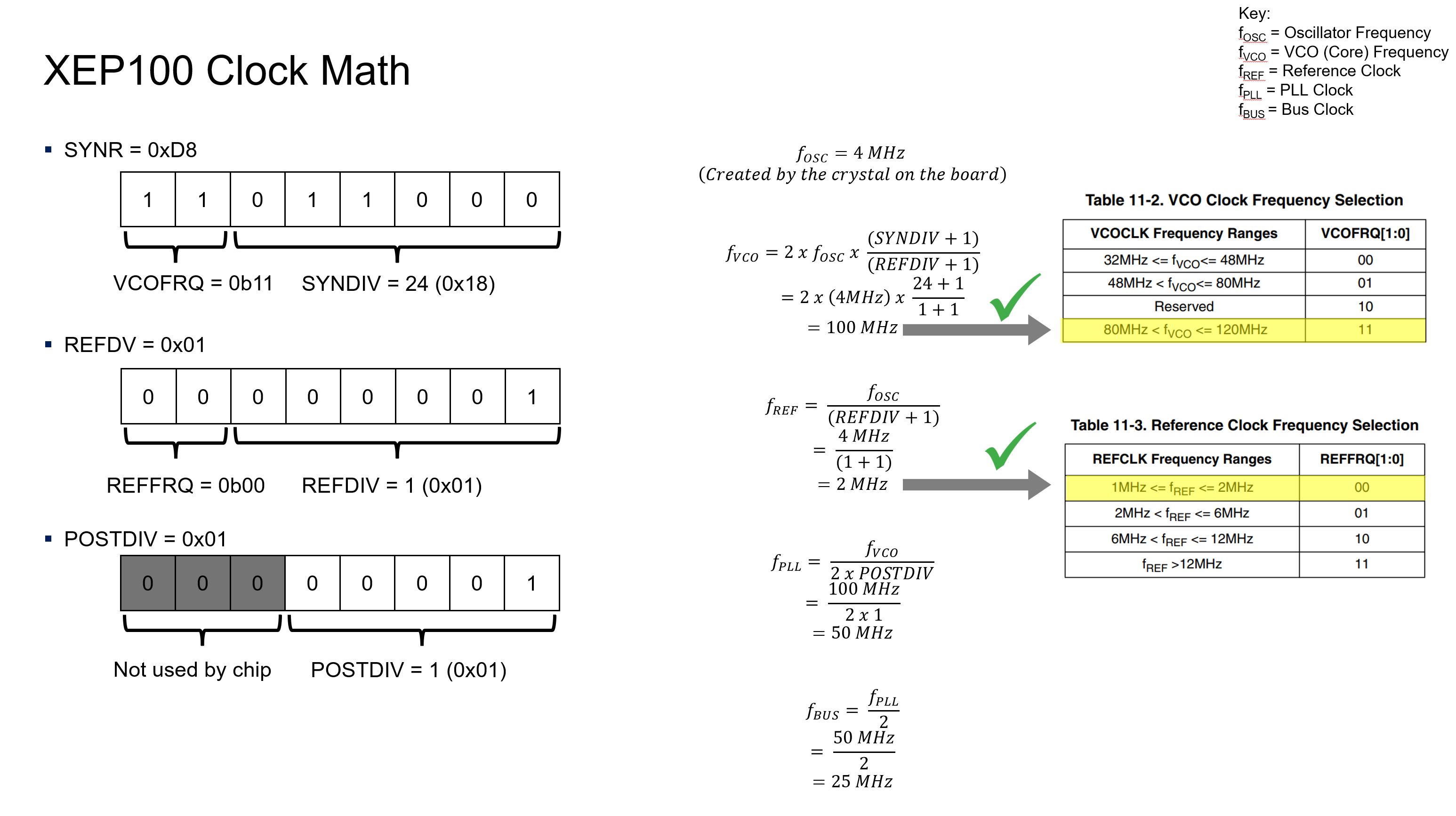
SYNR = 0xD8
REFDV = 0x01
POSTDIV = 0x01
Attached is a picture of the math based on these settings, but the summary is that we expect the bus clock to be 25MHz. However, when using a scope on Port PE4 with the ECLK enabled, we see a bus clock of 50MHz, double the expected.
The only working theory that we have is that Fosc is actually 8MHz instead of the 4MHz from the crystal. Is there something else that we missed? Any thoughts?
Thank you
解決済! 解決策の投稿を見る。
- 新着としてマーク
- ブックマーク
- 購読
- ミュート
- RSS フィードを購読する
- ハイライト
- 印刷
- 不適切なコンテンツを報告
Hi,
this MCU is from older set which enables you to check oscillator in special mode.
So easily, if you connect BDM to it and starts the MCU in special single chip mode (SSM) - standard debugging process when the MCU stops and waits for BDM command from the PC. In this case ECLKCTL_NECLK is set to 0 after reset which means you are able to check the OSCCLK/2 frequency at PE4 pin.
(Another approach to set the SSM is reset the MCU with pins MODC=MODB=MODA=0)
One more thing, could you please chceck whether you accidentally do not write PLLSEL=1 before you change PLL setup registers and/or you do not have already PLL set somewhere else in the code in some forgotten routine which sets the PLLSEL to 1 (start12.c,....) .
Best regards,
Ladislav
- 新着としてマーク
- ブックマーク
- 購読
- ミュート
- RSS フィードを購読する
- ハイライト
- 印刷
- 不適切なコンテンツを報告
Thanks for your advice. I was able to connect to the BDM and read the OSSCLK/2 as 4MHz, putting OSSCLK at 8MHz. This confirms our theory that the OSSCLK is double the physical crystal frequency on our board. (And thankfully no, I did not have any errant settings of the PLL registers)
I think we are all set now, thank you again for all your help!
- 新着としてマーク
- ブックマーク
- 購読
- ミュート
- RSS フィードを購読する
- ハイライト
- 印刷
- 不適切なコンテンツを報告
Hi,
Your calculation is ok. You can check it with calculator:
https://community.nxp.com/t5/S12-MagniV-Microcontrollers/S12X-PLL-Filter-Calculator/ta-p/1125313
Download S12XE_iPLL_Calc_103.exe from attachments at the page
It would be good to check whether the oscillator uses the first harmonics. Also it is good to be sure the load capacitance is correctly calculated. For Pierce circuitry the load capacitors must be C1=C2 > 2*CL where CL is a load capacitance of the oscillator provided in the oscillator data sheet.
Finally, be sure you really measure ECLK and not ECLKX2..... (I know you wrote PE4 but it already happened that HW eng. accidentally connected to the check pin ECLKX2)
(Note, there are some examples from my history at https://community.nxp.com/t5/S12-MagniV-Microcontrollers/LAMA-s-S12XE-unofficial-examples/ta-p/11007... )
Best regards,
Ladislav
- 新着としてマーク
- ブックマーク
- 購読
- ミュート
- RSS フィードを購読する
- ハイライト
- 印刷
- 不適切なコンテンツを報告
Ladislav,
Thank you for the information.
I would assume that the load capacitance is correctly calculated as we are using an evaluation board as sold by NXP with no modifications. Your suggestion about the first harmonic is intriguing though. How would I go about checking that?
And thank you for all your example code, I have used it as a reference for a couple projects.
Kind regards,
Kyle