
- NXP Forums
- Product Forums
- General Purpose MicrocontrollersGeneral Purpose Microcontrollers
- i.MX Forumsi.MX Forums
- QorIQ Processing PlatformsQorIQ Processing Platforms
- Identification and SecurityIdentification and Security
- Power ManagementPower Management
- MCX Microcontrollers
- S32G
- S32K
- S32V
- MPC5xxx
- Other NXP Products
- Wireless Connectivity
- S12 / MagniV Microcontrollers
- Powertrain and Electrification Analog Drivers
- Sensors
- Vybrid Processors
- Digital Signal Controllers
- 8-bit Microcontrollers
- ColdFire/68K Microcontrollers and Processors
- PowerQUICC Processors
- OSBDM and TBDML
-
- Solution Forums
- Software Forums
- MCUXpresso Software and ToolsMCUXpresso Software and Tools
- CodeWarriorCodeWarrior
- MQX Software SolutionsMQX Software Solutions
- Model-Based Design Toolbox (MBDT)Model-Based Design Toolbox (MBDT)
- FreeMASTER
- eIQ Machine Learning Software
- Embedded Software and Tools Clinic
- S32 SDK
- S32 Design Studio
- Vigiles
- GUI Guider
- Zephyr Project
- Voice Technology
- Application Software Packs
- Secure Provisioning SDK (SPSDK)
- Processor Expert Software
-
- Topics
- Mobile Robotics - Drones and RoversMobile Robotics - Drones and Rovers
- NXP Training ContentNXP Training Content
- University ProgramsUniversity Programs
- Rapid IoT
- NXP Designs
- SafeAssure-Community
- OSS Security & Maintenance
- Using Our Community
-
- Cloud Lab Forums
-
- Home
- :
- 製品フォーラム
- :
- S12 / MagniVマイクロコントローラ
- :
- Pin interrupt run abnormally
Pin interrupt run abnormally
- RSS フィードを購読する
- トピックを新着としてマーク
- トピックを既読としてマーク
- このトピックを現在のユーザーにフロートします
- ブックマーク
- 購読
- ミュート
- 印刷用ページ
Pin interrupt run abnormally
- 新着としてマーク
- ブックマーク
- 購読
- ミュート
- RSS フィードを購読する
- ハイライト
- 印刷
- 不適切なコンテンツを報告
Hi,
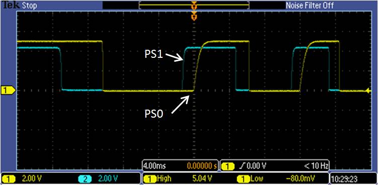
I use PS0 and PS1 to get the direction and counts about two pulses whose timing diagram is shown in attachment. Enable the PS0 and PS1 pin interrupt. The polarity of the active edge is like that: PS0 select rising edge, PS1 select falling edge. When a valid edge on an input is detected, read the port data about the other. My code is like that:
void port_init(void)
{
DDRS = 0x0; /* PS[3:0] are configured as input */
PPSS = 0x1; /* Rising edge: PS0 Falling edge: PS1 */
PIFS = 0x3; /* Clear PS0, PS1(KWU) flag */
PIES = 0x3; /* Enable PS0, PS1 interrupt(KWU) */
}
void knob_detect(void)
{
if (PIFS_PIFS0 == 1 && PIFS_PIFS1 == 0)
{
if (PTS_PTS1 == 1) /* Rotate the volume knob up in the first case */
{
MSG_1.Byte0_0.Bits.VolAdj ++; /* ① */
}
else /* Rotate the volume knob down in the first case */
{
MSG_1.Byte0_0.Bits.VolAdj --; /* ② */
}
}
if (PIFS_PIFS0 == 0 && PIFS_PIFS1 == 1)
{
if (PTS_PTS0 == 1) /* Rotate the volume knob up in the second case */
{
MSG_1.Byte0_0.Bits.VolAdj ++; /* ③ */
}
else /* Rotate the volume knob down in the second case */
{
MSG_1.Byte0_0.Bits.VolAdj --; /* ④ */
}
}
}
void interrupt VectorNumber_Vports key_wakeup_ISR(void)
{
knob_detect();
}
/*==============================================================*/
The debug result is: the software only enter the code ④, can't enter the code ①, ②, ③.
Then I try to change the polarity of the active edge, the code updated is like that:
void port_init(void)
{
DDRS = 0x0; /* PS[3:0] are configured as input */
PPSS = 0x2; /* Falling edge: PS0 Rising edge: PS1 */
PIFS = 0x3; /* Clear PS0, PS1(KWU) flag */
PIES = 0x3; /* Enable PS0, PS1 interrupt(KWU) */
}
void knob_detect(void)
{
if (PIFS_PIFS0 == 1 && PIFS_PIFS1 == 0)
{
if (PTS_PTS1 == 0) /* Rotate the volume knob up in the first case */
{
MSG_1.Byte0_0.Bits.VolAdj ++; /* ① */
}
else /* Rotate the volume knob down in the first case */
{
MSG_1.Byte0_0.Bits.VolAdj --; /* ② */
}
}
if (PIFS_PIFS0 == 0 && PIFS_PIFS1 == 1)
{
if (PTS_PTS0 == 0) /* Rotate the volume knob up in the second case */
{
MSG_1.Byte0_0.Bits.VolAdj ++; /* ③ */
}
else /* Rotate the volume knob down in the second case */
{
MSG_1.Byte0_0.Bits.VolAdj --; /* ④ */
}
}
}
void interrupt VectorNumber_Vports key_wakeup_ISR(void)
{
knob_detect();
}
/*==============================================================*/
The debug result is: the software can enter code ①, ②, ③, ④.
It seems that the polarity of PS0 can't select rising edge, is it correct about my guess?
Please help me, thanks!
- 新着としてマーク
- ブックマーク
- 購読
- ミュート
- RSS フィードを購読する
- ハイライト
- 印刷
- 不適切なコンテンツを報告
Hi,
I have not tested yet but tried to adjust similar code I used for port P:
void interrupt 56 DP_DoorProcessing_ISR(void) // port P interrupt for rising and fallling edges
{
static UBYTE flags = 0; // static, for other purposes if you want to know last status
flags = PIFP & 0x03; // store current status of flags and filter last two bits
PIFP = 0xFF; // Clear all pending interrupts
if( flags == 0x03 ) // both rising and falling edge has happened in observed period
{
// check status of both pulses
// we know the signal at PTP.0 is low because if edge type
// we know the signal at PTP.1 is high because of edge type
}
else
{
if (flags & 0x01) // only falling edge at PTP.0
{
// we know the signal at PTP.0 is low
// check level of signal at PTP.1
(PTP_PTP1) ? (MSG_1.Byte0_0.Bits.VolAdj --) : (MSG_1.Byte0_0.Bits.VolAdj ++)
}
else // only rising edge at PTP.1
{
// we know the signal at PTP.1 is high
// check level of signal at PTP.0
(PTP_PTP0) ? (MSG_1.Byte0_0.Bits.VolAdj --) : (MSG_1.Byte0_0.Bits.VolAdj ++)
}
}
}
void DOOR0_PIN_INIT(void) // input pin, pull, up, falling
{ DDRP_DDRP0=INPUT;
PERP_PERP0=PULLENA;
PPSP_PPSP0=PULLUPFALLINGEDGE;
}
void DOOR1_PIN_INIT(void) // input pin, nopull, down, rising
{
DDRP_DDRP1=INPUT;
PERP_PERP1=PULLENA;
PPSP_PPSP1=PULLDWNRISINGEDGE;
}
Best regards,
Ladislav
- 新着としてマーク
- ブックマーク
- 購読
- ミュート
- RSS フィードを購読する
- ハイライト
- 印刷
- 不適切なコンテンツを報告
Hi,
I cannot see your code where you should clear interrupt flags.
So, the ④ is the first and simultaneously last valid captured edge. The next edge (when PS0 go up) will set PIFS_PIFS1 flag and you will end with unhandled case where PIFS_PIFS0 == 1 && PIFS_PIFS1 == 1.
Since you do not clear flags, the interrupt routine is executed again and again.
You may use for example:
void knob_detect(void)
{
if (PIFS_PIFS0 == 1 && PIFS_PIFS1 == 0)
{
if (PTS_PTS1 == 0) /* Rotate the volume knob up in the first case */
{
MSG_1.Byte0_0.Bits.VolAdj ++; /* ① */
}
else /* Rotate the volume knob down in the first case */
{
MSG_1.Byte0_0.Bits.VolAdj --; /* ② */
}
PIFS = 0x01; //clear PIFS_PIFS0 flag
}
if (PIFS_PIFS0 == 0 && PIFS_PIFS1 == 1)
{
if (PTS_PTS0 == 0) /* Rotate the volume knob up in the second case */
{
MSG_1.Byte0_0.Bits.VolAdj ++; /* ③ */
}
else /* Rotate the volume knob down in the second case */
{
MSG_1.Byte0_0.Bits.VolAdj --; /* ④ */
}
PIFS = 0x02; //clear PIFS_PIFS1 flag
}
}
Note: there still may remain unusual case when both flags are set – for example when interrupt routine is executed with delay due to previous interrupt.
Note: Please do not use commands like PIFS_PIFS0 = 1;. This command is executed as read/modify/write operation on whole register. This way we clear all pending flags in this register.
More details may be found in AN2554 Clearing and Disabling Interrupt Flags.
I hope it helps you.
Best regards
Radek
- 新着としてマーク
- ブックマーク
- 購読
- ミュート
- RSS フィードを購読する
- ハイライト
- 印刷
- 不適切なコンテンツを報告
Hi Radek,
Sorry, I forgot to put this code which is uesd to clear interrupt flags here. My whole code is that:
void knob_detect(void)
{
if (PIFS_PIFS0 == 1 && PIFS_PIFS1 == 0)
{
if (PTS_PTS1 == 1) /* Rotate the volume knob up in the first case */
{
if (MSG_1.Byte0_0.Bits.VolAdj < 0x18)
{
MSG_1.Byte0_0.Bits.VolAdj ++;
}
}
else /* Rotate the volume knob down in the first case */
{
if (MSG_1.Byte0_0.Bits.VolAdj > 0x0)
{
MSG_1.Byte0_0.Bits.VolAdj --;
}
}
}
if (PIFS_PIFS0 == 0 && PIFS_PIFS1 == 1)
{
if (PTS_PTS0 == 1) /* Rotate the volume knob up in the second case */
{
if (MSG_1.Byte0_0.Bits.VolAdj < 0x18)
{
MSG_1.Byte0_0.Bits.VolAdj ++;
}
}
else /* Rotate the volume knob down in the second case */
{
if (MSG_1.Byte0_0.Bits.VolAdj > 0x0)
{
MSG_1.Byte0_0.Bits.VolAdj --;
}
}
}
PIFS = 0x3; /* Clear all the flag */
}
I also try to debug it as your example, but it still run abnormally: it only enter the code ④, can't enter the code ①, ②, ③.
I wonder that why it run normally when I change the polarity of the active edge and update the knob_detect function:
PS0 rising edge => falling edge
PS1 falling edge => rising edge
void knob_detect(void)
{
if (PIFS_PIFS0 == 1 && PIFS_PIFS1 == 0)
{
if (PTS_PTS1 == 0) /* Rotate the volume knob up in the first case */
{
MSG_1.Byte0_0.Bits.VolAdj ++; /* ① */
}
else /* Rotate the volume knob down in the first case */
{
MSG_1.Byte0_0.Bits.VolAdj --; /* ② */
}
}
if (PIFS_PIFS0 == 0 && PIFS_PIFS1 == 1)
{
if (PTS_PTS0 == 0) /* Rotate the volume knob up in the second case */
{
MSG_1.Byte0_0.Bits.VolAdj ++; /* ③ */
}
else /* Rotate the volume knob down in the second case */
{
MSG_1.Byte0_0.Bits.VolAdj --; /* ④ */
}
}
PIFS = 0x3; /* Clear all the flag */
}
Besides, for note: there still may remain unusual case when both flags are set – for example when interrupt routine is executed with delay due to previous interrupt.
=> Through the timing diagram we can see the length between rising edge and falling edge is much more than 1ms. It is enough for interrupt routine to be executed. For the worst case, if both flags are set because of unusual case, this command (PIFS = 0x3) can ensure that the interrupt routine will not be executed again and again.
For note: Please do not use commands like PIFS_PIFS0 = 1;. This command is executed as read/modify/write operation on whole register. This way we clear all pending flags in this register.
=> I think the command that write "1" to PIFS should be placed in the end. Then it will not impact on the other codes which are in the interrupt routine.
Could you help me to check what cause this problem? Many thanks!
Best regards
Jeff
- 新着としてマーク
- ブックマーク
- 購読
- ミュート
- RSS フィードを購読する
- ハイライト
- 印刷
- 不適切なコンテンツを報告
Hi Jeff,
In fact, I am not sure, what is the root cause.
There shouldn’t be any significant difference between these pins on MCU side.
Are both pins configured the same way (except edge polarity)?
Strange are different voltage levels and edge shapes since I supposed that both signals come from the same encoder.
Is any other circuit connected to these pins?
About case when both flags are set)
I mean here that theoretically some another interrupt (like PIT/SCI/CAN,...) may be longer that this 1ms.
Ideas:
For testing purposes, could you please use some simple variable for debugging instead of structure with VolAdj?
For example:
volatile unsigned char MyVolAdj;
Some if/else trees may be optimized by compiler, please try add asm NOP; commands into this tree for temporary avoiding optimizing.
I hope it helps you.
Best regards
Radek