
- Forums
- Product Forums
- General Purpose MicrocontrollersGeneral Purpose Microcontrollers
- i.MX Forumsi.MX Forums
- QorIQ Processing PlatformsQorIQ Processing Platforms
- Identification and SecurityIdentification and Security
- Power ManagementPower Management
- MCX Microcontrollers
- S32G
- S32K
- S32V
- MPC5xxx
- Other NXP Products
- Wireless Connectivity
- S12 / MagniV Microcontrollers
- Powertrain and Electrification Analog Drivers
- Sensors
- Vybrid Processors
- Digital Signal Controllers
- 8-bit Microcontrollers
- ColdFire/68K Microcontrollers and Processors
- PowerQUICC Processors
- OSBDM and TBDML
-
- Solution Forums
- Software Forums
- MCUXpresso Software and ToolsMCUXpresso Software and Tools
- CodeWarriorCodeWarrior
- MQX Software SolutionsMQX Software Solutions
- Model-Based Design Toolbox (MBDT)Model-Based Design Toolbox (MBDT)
- FreeMASTER
- eIQ Machine Learning Software
- Embedded Software and Tools Clinic
- S32 SDK
- S32 Design Studio
- GUI Guider
- Zephyr Project
- Voice Technology
- Application Software Packs
- Secure Provisioning SDK (SPSDK)
- Processor Expert Software
- MCUXpresso Training Hub
-
- Topics
- Mobile Robotics - Drones and RoversMobile Robotics - Drones and Rovers
- NXP Training ContentNXP Training Content
- University ProgramsUniversity Programs
- Rapid IoT
- NXP Designs
- SafeAssure-Community
- OSS Security & Maintenance
- Using Our Community
-
- Cloud Lab Forums
-
- Knowledge Bases
- ARM Microcontrollers
- i.MX Processors
- Identification and Security
- Model-Based Design Toolbox (MBDT)
- QorIQ Processing Platforms
- S32 Automotive Processing Platform
- Wireless Connectivity
- CodeWarrior
- MCUXpresso Suite of Software and Tools
- MQX Software Solutions
-
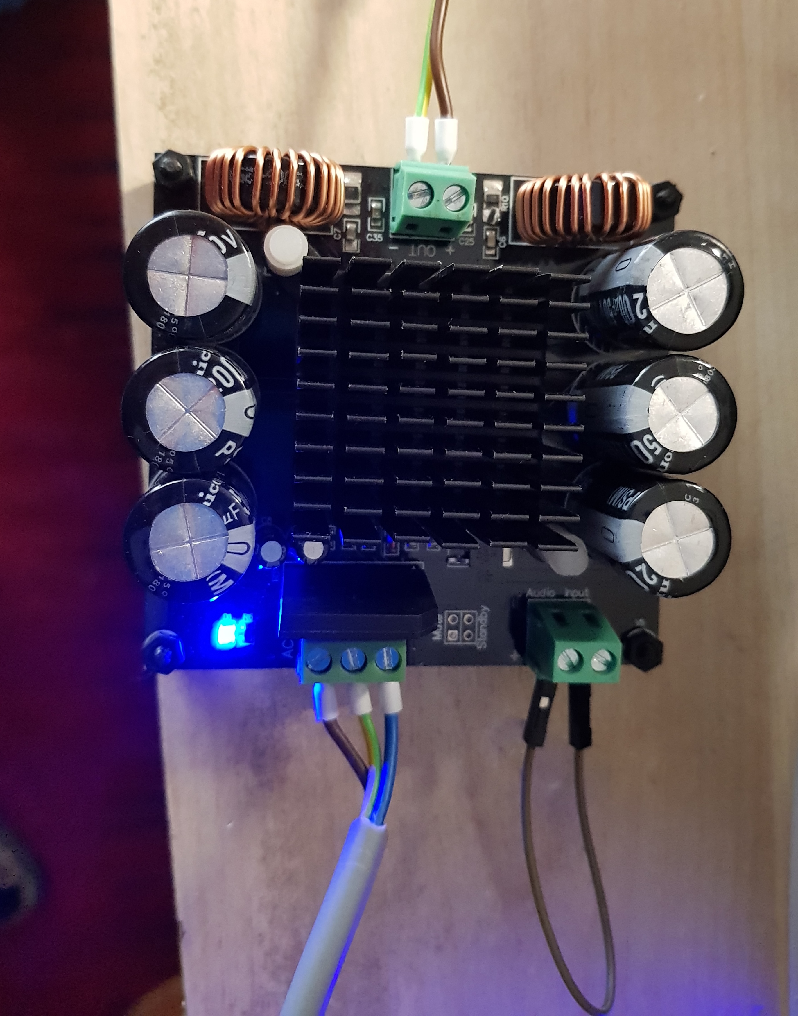
TDA8954TH
Recently I bought a Digital Amplifier Board TDA8954TH BTL Mode Module Board (<here> )
I connected
- PSU : 2x24VAC 2x4.2A (transformer)
- Output : Resistor 8Ohm
- Input : short circuit
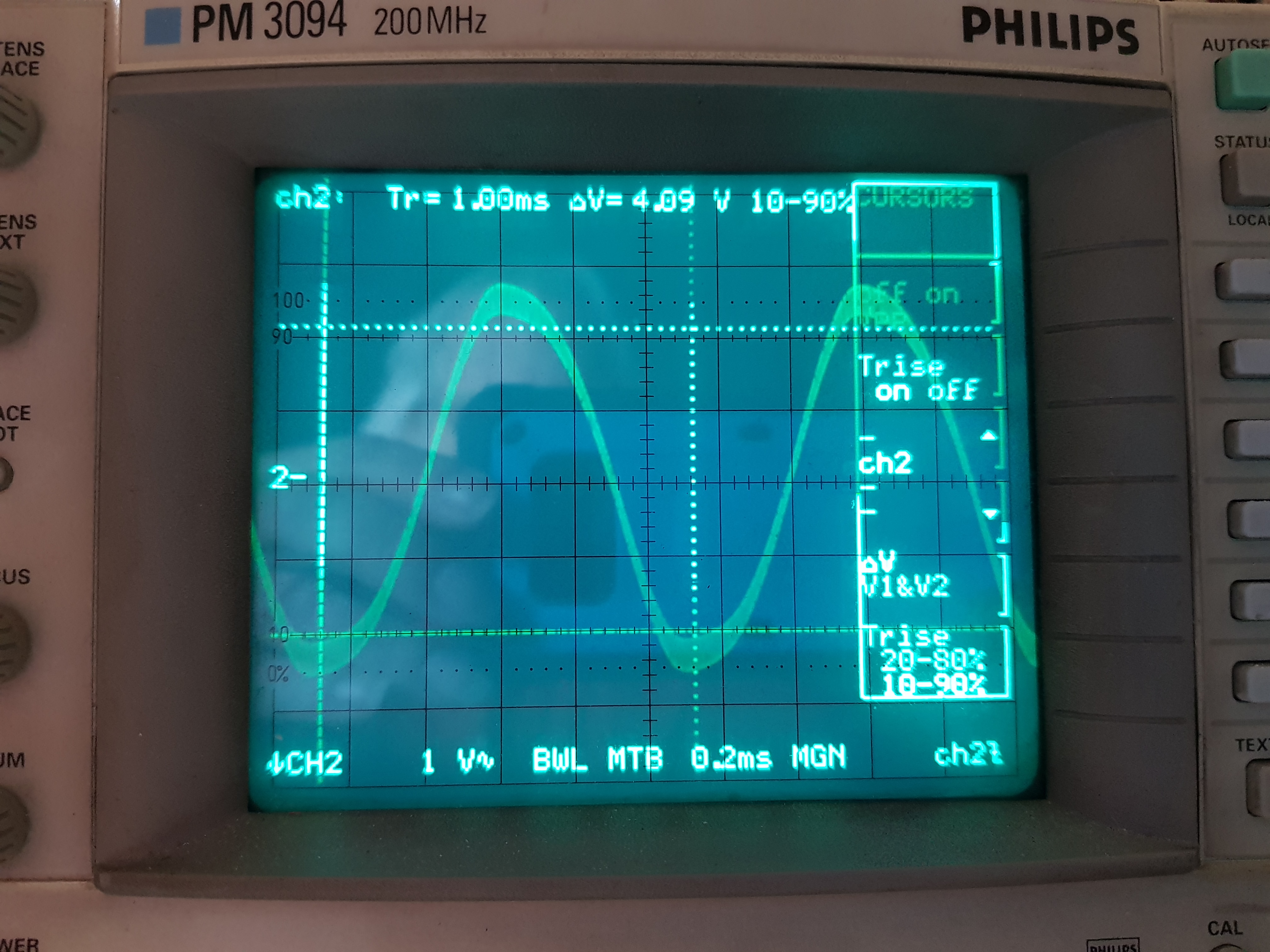
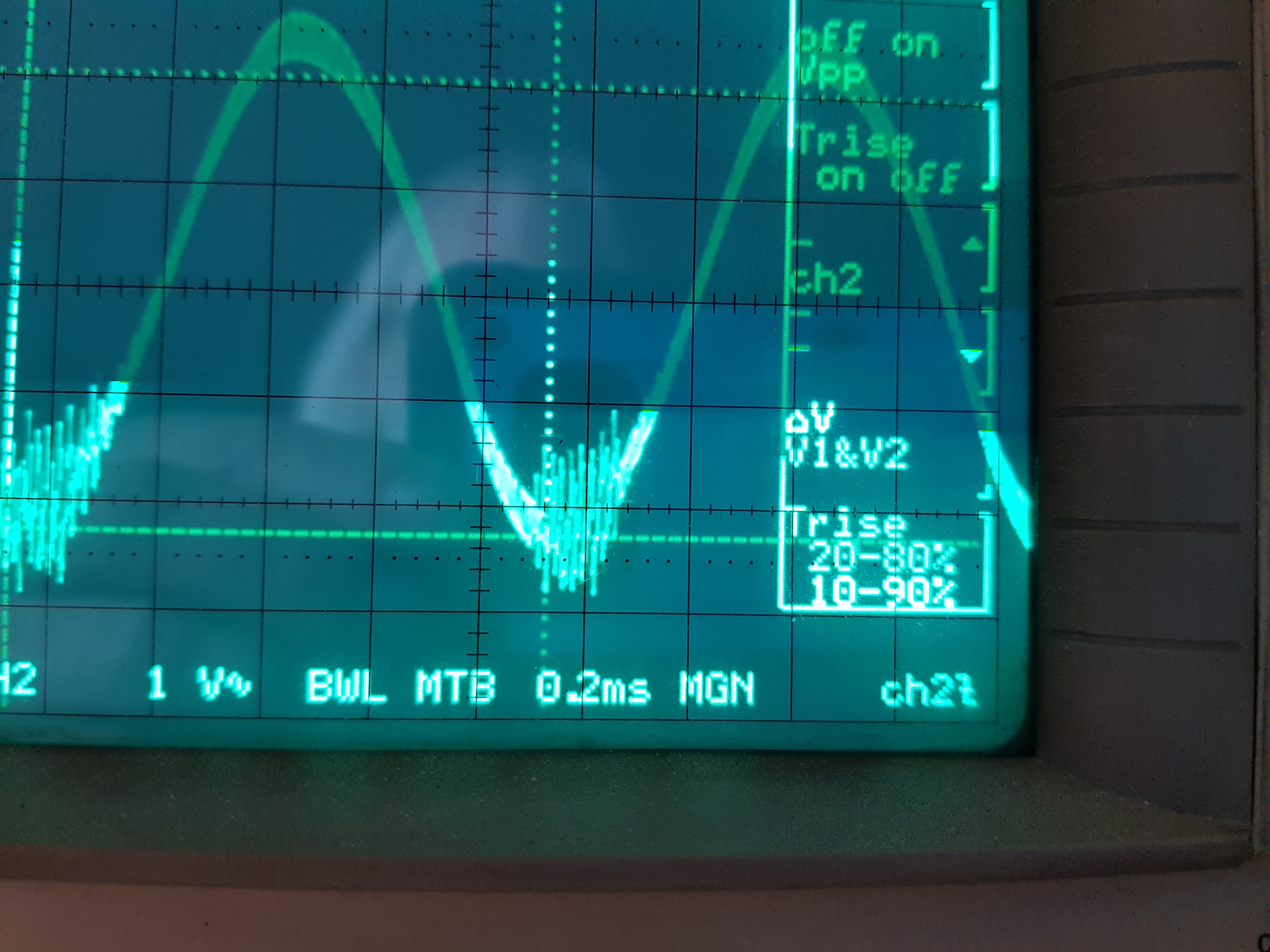
At the output I see on my oscilloscope a sine wave of about 1,5V/300KHz
When I connect a sine wave at the input, the 300KHz is added to the output.
When I raise the input to a certain point, a weird (and audible) oscillation appears at the bottom of the sinuses.
There is no change when I connect/disconnect ground (Earth) to any point.
What is wrong ?
Thanks in advance !
Need more info ? Ask !
Dear Jozef,
Thanks for the info. Don't worry about your late reply. I'd rather wait a little bit for a "good" answer than a fast reply with nothing interesting.
In the mean while I have done some more investigations. Sadly enough, I couldn't find any diagrams of "my" amp, so I ordered a few coils and capacitors to build an (extra) LC filter. "extra" because I could measure that the two coils on the board are (part of ?) the output filter.
I found e.g. https://www.ti.com/tool/LCFILTER-CALC-TOOL. to calculate the values of the L and C's. I'll start with using the BTL-Differential mode. Because the amp will be used mainly as Bass guitar amp, I filled in the spreadsheet and went for a cutoff frequency of 20KHz, so I bought a few coils and capacitors. (12µH , 10µH ,1.0µF 1.5µF ). I'll let you know the results of this filter(s) after the parts arrive. (probably next week) This doesn't mean that I want you to stop your engineers searching for a solution. I'm sure they'll come up with a (much!) better solution
Another thing that I really should mention :
I sent a complaint to the seller and guess what : They sent me a full refund !!
While anxiously waiting for your next reply : thanks again for your effort to solve my problem !
And of course : Friendly Greetings !
Wow !
Thanks Jozef !
I didn't completely release the "POST" button and there was your answer ! WOW !
The datasheet is certainly extremely interesting ! I downloaded it before, but skipped reading fig 13 because it is NOT BTL... So too bad that Fig13 is about a "Single ended" amp. I'm not sure how to "translate" this to a BTL amp... This might be an interesting question for your engineers ... ???
I've seen fig.10 but there aren't any values ...
Nevertheless : 1K Thanks !!
Dear Paul,
what you hear on the output is probably the PWM signal, which should be demodulated by a second-order LC demodulation filter. It seems, the filter doesn't work correctly.

The connection of the board is very simple and if you are sure, that the supply power is stable, without any signal on the audio input there should be nothing on the audio output. Please see this video: https://www.youtube.com/watch?v=RZJgnAh0__k.
So if you are sure, that you are using the correct, stable supply power I can only recommend to return the board to the seller as faulty.
With Best Regards,
Jozef
Dear Paul,
I apologize for a late reply.
I have sent the request to an application engineer, but I haven't received an answer yet. As soon as I will receive one I will definitely reply to you.
Thank you for your patience.
With Best Regards,
Jozef