- Forums
- Product Forums
- General Purpose MicrocontrollersGeneral Purpose Microcontrollers
- i.MX Forumsi.MX Forums
- QorIQ Processing PlatformsQorIQ Processing Platforms
- Identification and SecurityIdentification and Security
- Power ManagementPower Management
- Wireless ConnectivityWireless Connectivity
- RFID / NFCRFID / NFC
- Advanced AnalogAdvanced Analog
- MCX Microcontrollers
- S32G
- S32K
- S32V
- MPC5xxx
- Other NXP Products
- S12 / MagniV Microcontrollers
- Powertrain and Electrification Analog Drivers
- Sensors
- Vybrid Processors
- Digital Signal Controllers
- 8-bit Microcontrollers
- ColdFire/68K Microcontrollers and Processors
- PowerQUICC Processors
- OSBDM and TBDML
- S32M
- S32Z/E
-
- Solution Forums
- Software Forums
- MCUXpresso Software and ToolsMCUXpresso Software and Tools
- CodeWarriorCodeWarrior
- MQX Software SolutionsMQX Software Solutions
- Model-Based Design Toolbox (MBDT)Model-Based Design Toolbox (MBDT)
- FreeMASTER
- eIQ Machine Learning Software
- Embedded Software and Tools Clinic
- S32 SDK
- S32 Design Studio
- GUI Guider
- Zephyr Project
- Voice Technology
- Application Software Packs
- Secure Provisioning SDK (SPSDK)
- Processor Expert Software
- Generative AI & LLMs
-
- Topics
- Mobile Robotics - Drones and RoversMobile Robotics - Drones and Rovers
- NXP Training ContentNXP Training Content
- University ProgramsUniversity Programs
- Rapid IoT
- NXP Designs
- SafeAssure-Community
- OSS Security & Maintenance
- Using Our Community
-
- Cloud Lab Forums
-
- Knowledge Bases
- ARM Microcontrollers
- i.MX Processors
- Identification and Security
- Model-Based Design Toolbox (MBDT)
- QorIQ Processing Platforms
- S32 Automotive Processing Platform
- Wireless Connectivity
- CodeWarrior
- MCUXpresso Suite of Software and Tools
- MQX Software Solutions
- RFID / NFC
- Advanced Analog
-
- NXP Tech Blogs
- Home
- :
- 基于模型的设计工具箱(MBDT)
- :
- 基于模型的设计工具箱(MBDT)
- :
- UART communication failed
UART communication failed
Dear NXP,
I use example project "s32k3xx_uart_buffer_s32ct", which can work normally.
I need use the other UART pin, so I config the other pins.
I didn’t change the block structure.
Just only added the UART channel2 I needed and applied it.
When I use it, that project can't trigger interrupt.
I guess It wasn’t assigned to an interrupt.
Can you help me to solve, please?
Thanks
#UART #CommunicationFailed
已解决! 转到解答。
Hi, @SuperBeginner,
I downloaded the archive sent by you and, with some small changes, I managed to use the configured LPUART_0 instance to send and receive data in the loopback model.
What I noticed and some small mentions:
- The model uses an older version of RTD (3.0.0) and it was necessary to migrate to the new RTD (4.0.0). I suppose that this aspect may come from the prior use of the previous toolbox (1.4.0). This is where the problems you previously mentioned can also appear. So as a recommendation, try to use only one version of Toolbox in the MATLAB path.
- After the migration was done successfully, I was able to generate code based on the configuration. The configuration is done correctly, so there was no need to make any changes to it.
- Taking into account that the LPUART_6 instance used in the default configuration has the Rx and Tx pins directly connected to OpenSDA, so no additional connection is needed to use this LPUART instance, once OpenSDA is used.
- Instead, to use another instance of LPUART, an additional connection of the configured Rx and Tx pins is needed. An USB2Serial Converter can be used for this procedure. The Tx pin on the board connects to the Rx pin on the USB2Serial Converter, and the Rx pin on the board connects to the Tx pin on the USB2Serial Converter.
- So TXD pin 4 in the image above connects to PTA28 pin on the board (J412.23), and RXD pin 5 in the image above connects to PTA27 pin on the board (J3.20).
- After the connections are made successfully and the model is downloaded to the board, in the serial communication tool (for example RealTerm) connect the port corresponding to the USB2Serial Convert, NOT the board port, these ports being separate, but since we want the communication to be carried out using this converter, will connect to the port related to the converter.
After all these connections made successfully, you should be able to successfully communicate using the LPUART_0 instance.
I am attaching the updated model configuration for reference.
Hope this helps,
Dragos
Hi, @SuperBeginner.,
To change the LPUART instance used, LPUART_0 in your case, the following steps need to be followed:
- Make sure that the pins are available, not being used by another peripheral, and are correctly configured in the Port tab and in the Pins tab.
- Make sure that the instance you want to configure is correctly referenced to the clock value. You have selected UART_CLK, which is set to AIPS_SLOW_CLK. Based on the following table from the S32K3xx Reference Manual, the LPUART_0 is clocked by AIPS_PLAT_CLK. So you should either create a new clock, or modify the current value, but take into account this aspect of the clock at which each instance operates.
- You should enable the corresponding peripheral clock in the Mcu tab, in this case LPUART_0.
- Make sure that the interrupt is enabled for the corresponding instance, in this case LPUART0_IRQn, and set the Handler accordingly (LPUART_UART_IP_0_IRQHandler).
With these aspects in mind, you should successfully use the newly configured LPUART instance.
Hope this helps,
Dragos
Hi @dragostoma ,
Thank you for your reply.
Please forgive me as I am a beginner.
Can you tell me how to create a new clock which is AIPS_SLOW_CLK?
I also want to know how to enable the corresponding peripheral clock in the MCU tab and how to configure IRQ interrupts (LPUART0_IRQn & LPUART_UART_IP_0_IRQHander).
Thanks
Hi, @SuperBeginner,
1. MCU Clock Reference
To create a new clock reference or modify the already existing ones, you should access the following path in the configuration tool:
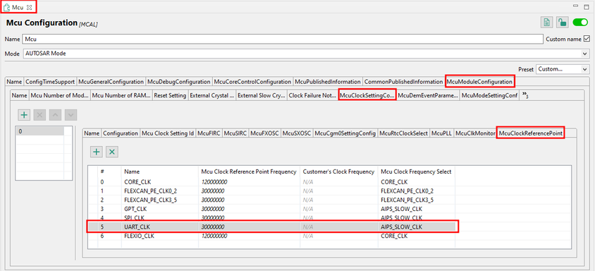
Mcu tab -> McuModuleConfiguration tab -> McuClockSettingConfig tab -> McuClockReferencePoint tab
Here you will find all the references of the clocks:
As mentioned in the Reference Manual, S32K312 has only LPUART_0 that uses AIPS_PLAT_CLK, the rest of the instances use AIPS_SLOW_CLK.
So to make sure that the other instances can still be used successfully, you can create a new reference for the UART, clocked by AIPS_PLAT_CLK.
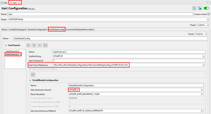
After that, you should make sure that the UART channel you want to use, which has the LPUART_0 instance set, uses the correct clock reference, the one we just created:
2. MCU Clock Enablement
To enable the clock of the peripheral you want to use, you should access the following path in the configuration tool:
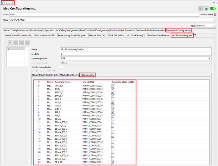
Mcu tab -> McuModuleConfiguration tab -> McuModeSettingConf tab -> McuPeripheral tab
Here you will find the list with all the available peripheral clocks.
To be able to use the new instance of LPUART, the related peripheral clock must be enabled.
3. Interrupts Configuration
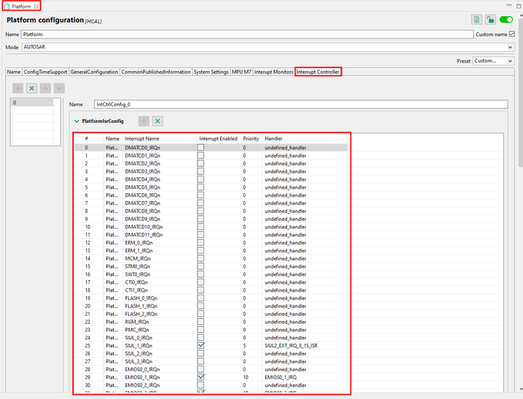
To be able to use the interrupt handlers, they must be enabled in the Platform tab, which can be found at the following path:
Platform tab -> Interrupt Controller tab
Here you will find the list with all the available interrupt handlers.
In order to be able to use the interrupt handler related to the LPUART_0 instance, it must be enabled, a priority must be set and it must be named based on the definition and implementation in the drivers MBDT generates code on top of. In this case will be LPUART_UART_IP_0_IRQHandler.
I hope this information clarifies the configuration and use of a new instance of LPUART.
Best regards,
Dragos
Hi, @dragostoma
I followed your suggestions and configured the newly added UART, but it still doesn't work. Attached is my file. Could you please help me check what might be the problem?
Thanks.
Hi, @SuperBeginner,
I downloaded the archive sent by you and, with some small changes, I managed to use the configured LPUART_0 instance to send and receive data in the loopback model.
What I noticed and some small mentions:
- The model uses an older version of RTD (3.0.0) and it was necessary to migrate to the new RTD (4.0.0). I suppose that this aspect may come from the prior use of the previous toolbox (1.4.0). This is where the problems you previously mentioned can also appear. So as a recommendation, try to use only one version of Toolbox in the MATLAB path.
- After the migration was done successfully, I was able to generate code based on the configuration. The configuration is done correctly, so there was no need to make any changes to it.
- Taking into account that the LPUART_6 instance used in the default configuration has the Rx and Tx pins directly connected to OpenSDA, so no additional connection is needed to use this LPUART instance, once OpenSDA is used.
- Instead, to use another instance of LPUART, an additional connection of the configured Rx and Tx pins is needed. An USB2Serial Converter can be used for this procedure. The Tx pin on the board connects to the Rx pin on the USB2Serial Converter, and the Rx pin on the board connects to the Tx pin on the USB2Serial Converter.
- So TXD pin 4 in the image above connects to PTA28 pin on the board (J412.23), and RXD pin 5 in the image above connects to PTA27 pin on the board (J3.20).
- After the connections are made successfully and the model is downloaded to the board, in the serial communication tool (for example RealTerm) connect the port corresponding to the USB2Serial Convert, NOT the board port, these ports being separate, but since we want the communication to be carried out using this converter, will connect to the port related to the converter.
After all these connections made successfully, you should be able to successfully communicate using the LPUART_0 instance.
I am attaching the updated model configuration for reference.
Hope this helps,
Dragos
Hi @dragostoma ,
Thanks for your help, I solved my problem.
But what I don’t understand is why if I add uart0 myself, I need to configure the freeMaster block to make my uart0 operate normally.
This is really confusing!
Hi, @SuperBeginner,
I'm glad to hear that you managed to solve the problem.
I hope I have correctly understood the confusion you have regarding the LPUART instance set in FreeMASTER, indeed, in order for the serial communication to work correctly, the LPUART instance on which the communication is to be carried out must be chosen. Since LPUART6 was set as the default instance for communication with FreeMASTER, having the Rx and Tx pins connected directly to OpenSDA and not needing additional connections, now if you want to use the newly configured instance, LPUART0, it must be set in the FreeMASTER Config block to ensure that the connection is made on the desired instance.
I hope I understood your problem correctly and I hope this clarifies the situation.
Best regards,
Dragos


