- NXP Forums
- Product Forums
- General Purpose MicrocontrollersGeneral Purpose Microcontrollers
- i.MX Forumsi.MX Forums
- QorIQ Processing PlatformsQorIQ Processing Platforms
- Identification and SecurityIdentification and Security
- Power ManagementPower Management
- MCX Microcontrollers
- S32G
- S32K
- S32V
- MPC5xxx
- Other NXP Products
- Wireless Connectivity
- S12 / MagniV Microcontrollers
- Powertrain and Electrification Analog Drivers
- Sensors
- Vybrid Processors
- Digital Signal Controllers
- 8-bit Microcontrollers
- ColdFire/68K Microcontrollers and Processors
- PowerQUICC Processors
- OSBDM and TBDML
-
- Solution Forums
- Software Forums
- MCUXpresso Software and ToolsMCUXpresso Software and Tools
- CodeWarriorCodeWarrior
- MQX Software SolutionsMQX Software Solutions
- Model-Based Design Toolbox (MBDT)Model-Based Design Toolbox (MBDT)
- FreeMASTER
- eIQ Machine Learning Software
- Embedded Software and Tools Clinic
- S32 SDK
- S32 Design Studio
- Vigiles
- GUI Guider
- Zephyr Project
- Voice Technology
- Application Software Packs
- Secure Provisioning SDK (SPSDK)
- Processor Expert Software
-
- Topics
- Mobile Robotics - Drones and RoversMobile Robotics - Drones and Rovers
- NXP Training ContentNXP Training Content
- University ProgramsUniversity Programs
- Rapid IoT
- NXP Designs
- SafeAssure-Community
- OSS Security & Maintenance
- Using Our Community
-
- Cloud Lab Forums
-
- RSS フィードを購読する
- トピックを新着としてマーク
- トピックを既読としてマーク
- このトピックを現在のユーザーにフロートします
- ブックマーク
- 購読
- ミュート
- 印刷用ページ
- 新着としてマーク
- ブックマーク
- 購読
- ミュート
- RSS フィードを購読する
- ハイライト
- 印刷
- 不適切なコンテンツを報告
Hello, dear working staffs and others,
I'm currently using the MPC5748G DEVKIT and I want to convert the analog signal from the peripheral potentiometer. I've checked several examples, but they are all using the Potentiometer on the board (ADC0 CH9).
Thus, I want to ask about the possibility to include the analog signal in PG13 and convert the signal using ADC1
And if possible, how should I know the corresponding channel number since I want to enable the channel but I can't find the information about the channel number.
ADC_DRV_EnableChannel(INST_ADCONV1, ADC_CONV_CHAIN_NORMAL, ADC_CHAN_NUM);
Best regards,
Zhengkun
解決済! 解決策の投稿を見る。
- 新着としてマーク
- ブックマーク
- 購読
- ミュート
- RSS フィードを購読する
- ハイライト
- 印刷
- 不適切なコンテンツを報告
Hello,
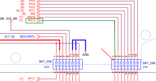
Simply connect your analog signal to pin header J14 pin 1.
Next you need to check internal routing of ADCs: In this case it is channel35
as you can see from routing table:
Last thing you need to se it APC bit in SUIL unit for corresponding MCSR register. Which is in this case MCSR 109.
After setting this you are ready for measurement of PG[13] channel via ADC1 channel 35.
Best regards,
Peter
- 新着としてマーク
- ブックマーク
- 購読
- ミュート
- RSS フィードを購読する
- ハイライト
- 印刷
- 不適切なコンテンツを報告
Thank you, this answer solved my problem perfectly
- 新着としてマーク
- ブックマーク
- 購読
- ミュート
- RSS フィードを購読する
- ハイライト
- 印刷
- 不適切なコンテンツを報告
Hello,
Simply connect your analog signal to pin header J14 pin 1.
Next you need to check internal routing of ADCs: In this case it is channel35
as you can see from routing table:
Last thing you need to se it APC bit in SUIL unit for corresponding MCSR register. Which is in this case MCSR 109.
After setting this you are ready for measurement of PG[13] channel via ADC1 channel 35.
Best regards,
Peter
- 新着としてマーク
- ブックマーク
- 購読
- ミュート
- RSS フィードを購読する
- ハイライト
- 印刷
- 不適切なコンテンツを報告
Thank you for your reply, now I got the ADC running.
But I still have some questions. According to the reference manual, the ADC1 should be a 12 bits ADC, but the conversion result I got is only 8 bits result. The input ranges from 0 volts to 3,3 volts.
Did I make the configuration wrong or the input voltage signal is not high enough? Could you please give me a hint?
Best regards!


