
- Forums
- Product Forums
- General Purpose MicrocontrollersGeneral Purpose Microcontrollers
- i.MX Forumsi.MX Forums
- QorIQ Processing PlatformsQorIQ Processing Platforms
- Identification and SecurityIdentification and Security
- Power ManagementPower Management
- Wireless ConnectivityWireless Connectivity
- RFID / NFCRFID / NFC
- Advanced AnalogAdvanced Analog
- MCX Microcontrollers
- S32G
- S32K
- S32V
- MPC5xxx
- Other NXP Products
- S12 / MagniV Microcontrollers
- Powertrain and Electrification Analog Drivers
- Sensors
- Vybrid Processors
- Digital Signal Controllers
- 8-bit Microcontrollers
- ColdFire/68K Microcontrollers and Processors
- PowerQUICC Processors
- OSBDM and TBDML
- S32M
- S32Z/E
-
- Solution Forums
- Software Forums
- MCUXpresso Software and ToolsMCUXpresso Software and Tools
- CodeWarriorCodeWarrior
- MQX Software SolutionsMQX Software Solutions
- Model-Based Design Toolbox (MBDT)Model-Based Design Toolbox (MBDT)
- FreeMASTER
- eIQ Machine Learning Software
- Embedded Software and Tools Clinic
- S32 SDK
- S32 Design Studio
- GUI Guider
- Zephyr Project
- Voice Technology
- Application Software Packs
- Secure Provisioning SDK (SPSDK)
- Processor Expert Software
- Generative AI & LLMs
-
- Topics
- Mobile Robotics - Drones and RoversMobile Robotics - Drones and Rovers
- NXP Training ContentNXP Training Content
- University ProgramsUniversity Programs
- Rapid IoT
- NXP Designs
- SafeAssure-Community
- OSS Security & Maintenance
- Using Our Community
-
- Cloud Lab Forums
-
- Knowledge Bases
- ARM Microcontrollers
- i.MX Processors
- Identification and Security
- Model-Based Design Toolbox (MBDT)
- QorIQ Processing Platforms
- S32 Automotive Processing Platform
- Wireless Connectivity
- CodeWarrior
- MCUXpresso Suite of Software and Tools
- MQX Software Solutions
- RFID / NFC
- Advanced Analog
-
- NXP Tech Blogs
- Home
- :
- MCUXpressoソフトウェアとツール
- :
- MCUXpressoコンフィグツール
- :
- Issue when using Config Tool to set up FlexIO
Issue when using Config Tool to set up FlexIO
- RSS フィードを購読する
- トピックを新着としてマーク
- トピックを既読としてマーク
- このトピックを現在のユーザーにフロートします
- ブックマーク
- 購読
- ミュート
- 印刷用ページ
- 新着としてマーク
- ブックマーク
- 購読
- ミュート
- RSS フィードを購読する
- ハイライト
- 印刷
- 不適切なコンテンツを報告
I'm using MCUXpresso version v11.7.0 and SDK version v2.13.0.
I'm attempting to configure FLEXIO2 in a configuration similar to the one described in AN5313 and am trying to set things up using the Periph Config Tool.
I want to parallel shift out 4-bits at a time (versus the 8 in the app note), but otherwise my needs are very similar to those in the app note.
I want to set it up so SHIFTERS[7:1] feed SHIFTER0, which outputs 4-bits per clock. DMA loads all of them.
Following the app note (and a zip file of the project that I downloaded), I'm trying to use the Peripheral Config Tool to create the register definitions, but find that the tool doesn't permit me to use combinations that the app note project suggests.
In particular, the app note uses SHIFTER0 to output data, and is fed from SHIFTER1. The other shifters are likewise loaded from their next-neighbor. All of the shifters are put in transmit mode.
So INSRC is set to '1' and SMOD is set to "010"
However, the tool will only let me set the shifter (1 to 7) input to the "next" shifter (resulting of INsrc=> '1') when the shifter is disabled (SMOD => "000"). When these shifters are put in "transmit" mode, the INSRC bit is set to '0'.
Similarly, the app note sets the width (PWIDTH) to the shift-out width (8 in the app note, 4 in my app) for all registers (again with all registers in "transmit" mode). It I attempt to put any value but 1 in the tool's width field for registers 1,2,3,5,6,7, I get a warning that they can't be used in parallel mode. This warning goes away if I these registers are set to "disabled", but the generated register value doesn't match what is produced for the app note.
Also, the app note sets the pin output configuration to "disabled" for shifters 1-7, but doing this with these registers set to "transmit" mode causes warnings, and again the generate register values don't match those for the app note.
I'm wondering if these are problems with the config tool, or if the app note app is setting some register fields that really aren't needed...
I'd like to use the Periph Config Tool, but am confused!
Thanks!
解決済! 解決策の投稿を見る。
- 新着としてマーク
- ブックマーク
- 購読
- ミュート
- RSS フィードを購読する
- ハイライト
- 印刷
- 不適切なコンテンツを報告
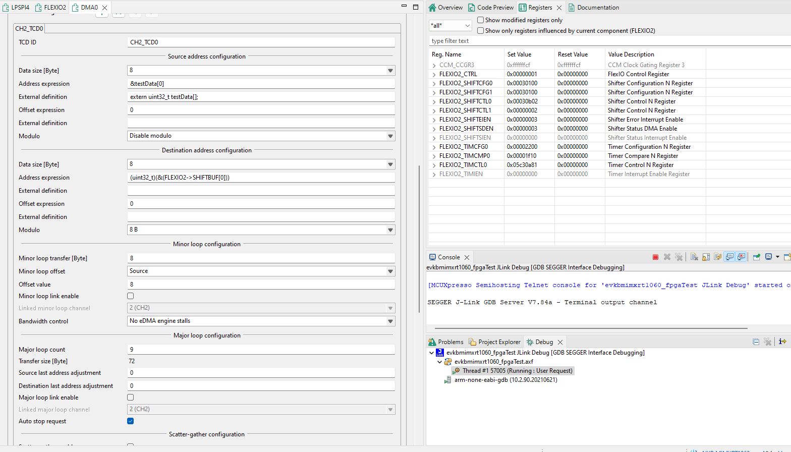
There is another box that must be checked to terminate DMA when the major loop count has been reached: "Auto Stop Request"
And the source address does not automatically continue from one minor loop to the next. The minor loop offset must be set for the source (in my case) to update the original address by the number of bytes transferred in the minor loop...
- 新着としてマーク
- ブックマーク
- 購読
- ミュート
- RSS フィードを購読する
- ハイライト
- 印刷
- 不適切なコンテンツを報告
Hello,
I forwarded your question to FlexIO Peripherals tool component developer for analysis.
Regards,
Lukas
- 新着としてマーク
- ブックマーク
- 購読
- ミュート
- RSS フィードを購読する
- ハイライト
- 印刷
- 不適切なコンテンツを報告
Hello,
I can confirm that the problem you are observing is a bug in the FlexIO registers initialization component. The Input source setting (INSRC) should be enabled also in the transfer mode.
I have created a hotfix resolving the issue in the FlexIO registers initialization component (MCUXpresso_Config_Tools_v13_FlexIO_reg_hotfix.zip). This hotfix is not yet fully tested. The final fully tested fix will be deployed in next update of MCUXpresso Config Tools.
Installation:
1. Ensure you have an administrator rights, MCUXpresso Configuration Tools are not running and the MCU data of the MCUs you want to use are available (downloaded) on your desktop.
2. Copy the content of this archive into the tool's data folder:
Windows: c:\ProgramData\NXP\mcu_data_v13
Linux/Mac: /home/<USER>/.nxp/mcu_data_v13
Thank you for your report and sorry for the inconvenience. Please let us know if you encounter any further issues.
Best Regards
Jan Kucera
Enablement team.
- 新着としてマーク
- ブックマーク
- 購読
- ミュート
- RSS フィードを購読する
- ハイライト
- 印刷
- 不適切なコンテンツを報告
Many thanks!
This fixed this problem!
Can I also suggest that when configuring the DMA channel associated with the FlexIO, the Major loop specifier be changed from [total] bytes to the number of times the major loop is traversed (loopCount).
Also, is there a GUI mechanism to set the Src/Dest Modulo for the DMA?
A problem I'm seeing: I'm using FLEXIO2 to send out 4-bit values. I have all of the shifters (7:0) linked together, so a "minor loop" traversal (one DMA burst) fills all 8 32-bit shiftbufs (32 bytes or 64 of my 4-bit values). The destination address is SHIFTBUF0 and the Destination Modulo is 32 bytes (so the second transfer also goes back to SHIFTBUF0). The source address is an array of uint_32_t.
I'm seeing the first 64 4-bit values shift out as expected, but the next 64 are a repeat of the first 64, and the 64 following that are also a repeat of the first 64, etc. It's as though the source DMA address goes back to the beginning of the array instead of marching through the uint_32_t array. I set the Source Modulo to 0. Did I miss a setting?
Thanks again!
- 新着としてマーク
- ブックマーク
- 購読
- ミュート
- RSS フィードを購読する
- ハイライト
- 印刷
- 不適切なコンテンツを報告
Hello,
Thank you for your feedback! From your description I assume that you are using transactional SDK API for your application. I recommend you to select in the Config Tools eDMA configuration component the "Channel API mode" to "Non-transactional (TCD structures)" mode in your eDMA channel configuration, which enables you to configure the complete transfer descriptor directly without using SDK API. By using SDK transactional API there are some limitations that are not supported.
In this mode the GUI allows you to configure the major loop count as you expect and also the source/destination modulo. The GUI setting for major loop in other API modes corresponds with the SDK API. As you suggest we can improve it by unifying the approach to expect the loop count as an input.
You can also select the quick selection preset to pre-configure some settings for this mode.

Regarding your problem I assume that you did not configured the source last address adjustment (SLAST) to be applied after the major loop completes. I think you want to move the SADDR after the major loop the the next 32 bytes of source array.
Best Regards,
Martin
- 新着としてマーク
- ブックマーク
- 購読
- ミュート
- RSS フィードを購読する
- ハイライト
- 印刷
- 不適切なコンテンツを報告
I'm still struggling with the setup of the DMA and FLEXIO2 to achieve the output that I need.
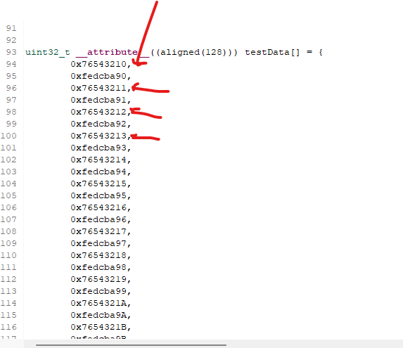
The attached images show the setup I'm using. I need to shift out around 133 4-bit values. I'm using the data shown in "TestData.png" as the values to be sent out.
The DMA is set up to point to item 0 (value 0x76543210) and the minor loop is set to fetch 8 bytes, so the second fetch should access the word pointed to by the second arrow (0x76543211), etc.
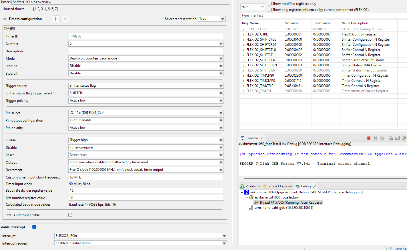
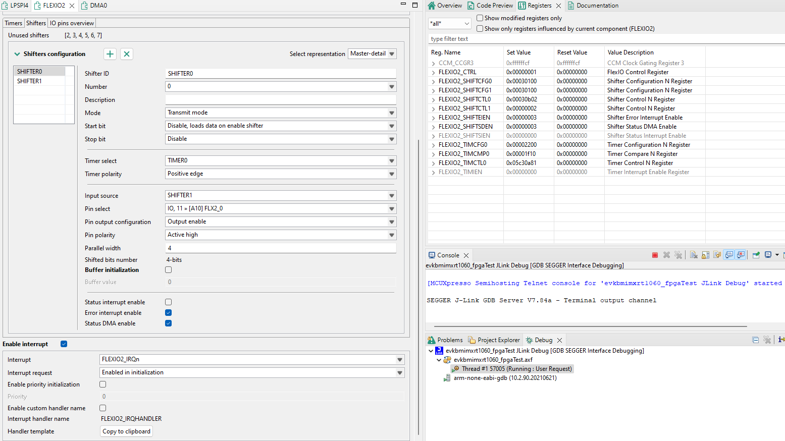
I'm using SHIFTER0 fed by SHIFTER1, so 8 bytes should be loaded into their SHIFTBUFs each DMA access. Each shift clock should deliver one 4-bit (nibble) value. I expect the second set of 8 bytes to load when the first set (of 8 bytes) is loaded into the shifters.
Since the minor loop loads 8 bytes (for 16 clocks), and the major loop is set to 9, I expect 72 bytes to be read and 144 4-bit values (slightly more than the 133 that I need) to be shifted.
What I'm seeing is:
1) The first 16 4-bit values are correct, but
2) The next 16 4-bit values come from (what should be) the 3rd DMA access (from where the 3rd arrow points (from word 0x76543212)
3) All other values are correctly fetched
4) I'm seeing 160 clocks (10 sets of 16 4-bit values) when I expect 144 (so there are 16 extra clocks)
5) I do see an interrupt that indicates that the DMA has completed, but this comes (as it should) before the shifter has finished... I need to be able to start the FLEXIO/DMA again with a different address when the original shifter has completed.
What am I doing wrong?
Thanks...
I'll add a reply post with one more image...
- 新着としてマーク
- ブックマーク
- 購読
- ミュート
- RSS フィードを購読する
- ハイライト
- 印刷
- 不適切なコンテンツを報告
- 新着としてマーク
- ブックマーク
- 購読
- ミュート
- RSS フィードを購読する
- ハイライト
- 印刷
- 不適切なコンテンツを報告
Hi there,
I can't see the root cause at the first sight. I just wonder, if you still call the software trigger as you posted in picture StartDMA.png. This might be the cause of the superfluous request. In your application code it is enough to call EDMA_EnableChannelRequest() function, that enables the peripheral request which is driven by FLEXIO peripheral.
I hope this helps you.
Martin
- 新着としてマーク
- ブックマーク
- 購読
- ミュート
- RSS フィードを購読する
- ハイライト
- 印刷
- 不適切なコンテンツを報告
Hi Martin,
Thanks for your suggestion!
I made the change to the TCD based setup, but am still not getting what I expected.
1) I want to be able to control when to start the transfer.
A) First I tried clicking the box "Peripheral request enable", but this started the transfers at boot time.
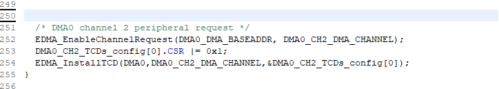
B) Then I tried using the code shown in the "StartDMA" image, but this only ran one minor loop until I added the first line shown there, but then it doesn't stop after the 4 iterations of the minor loop (Major Loop Count).
2) Watching the values on a logic analyzer, the values coming out for the first minor loop are correct, but as before, the other iterations of the minor loop give the same values as the first loop.
The manual seems to state that the LastAddressAdjustment is only applied after the last iteration of the Major Loop. Isn't the source address incremented after each access during the Minor Loop? So at the end of the Minor Loop accesses it points to the next uint32_t (to be accessed at the next iteration)?
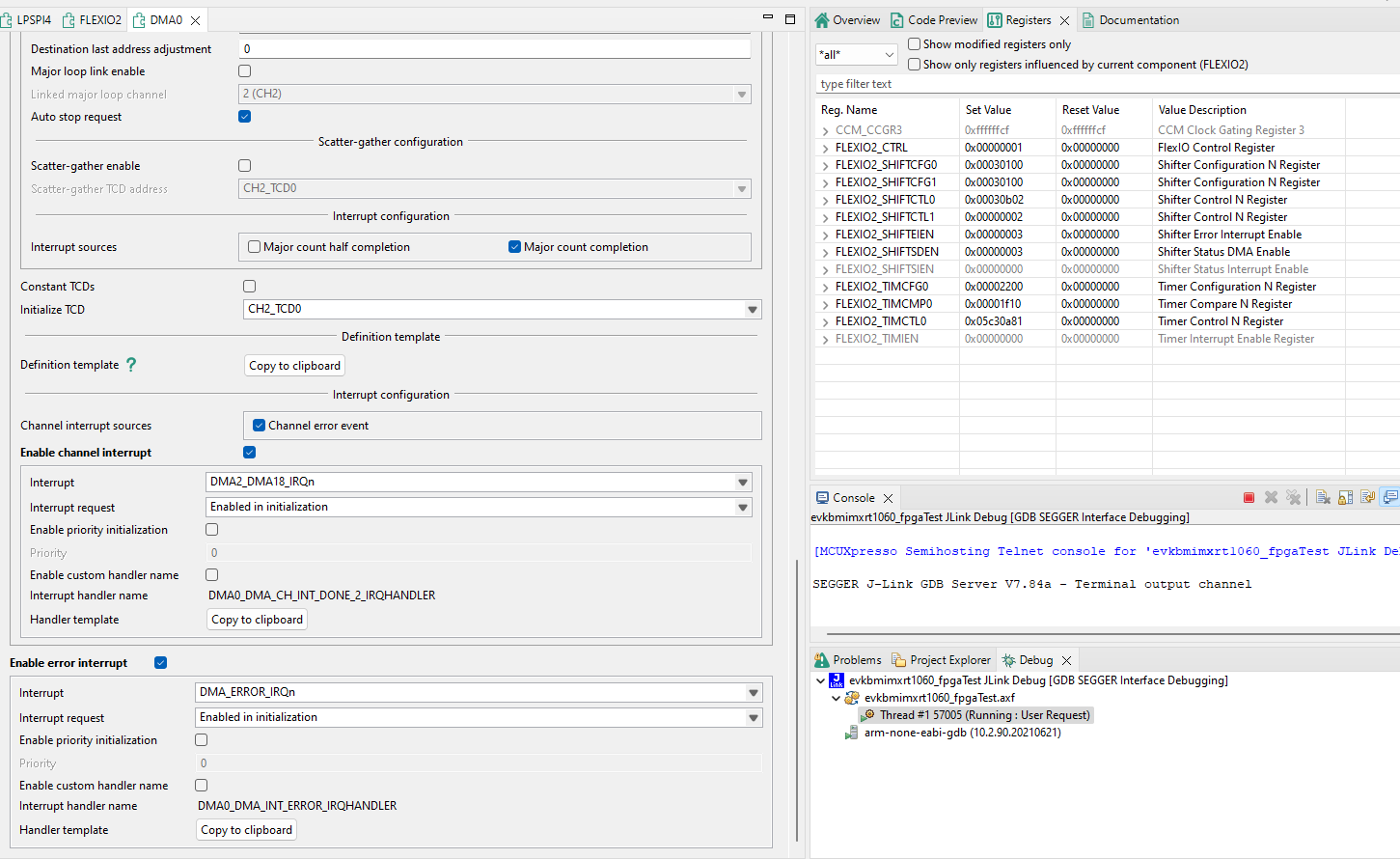
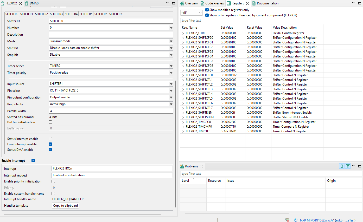
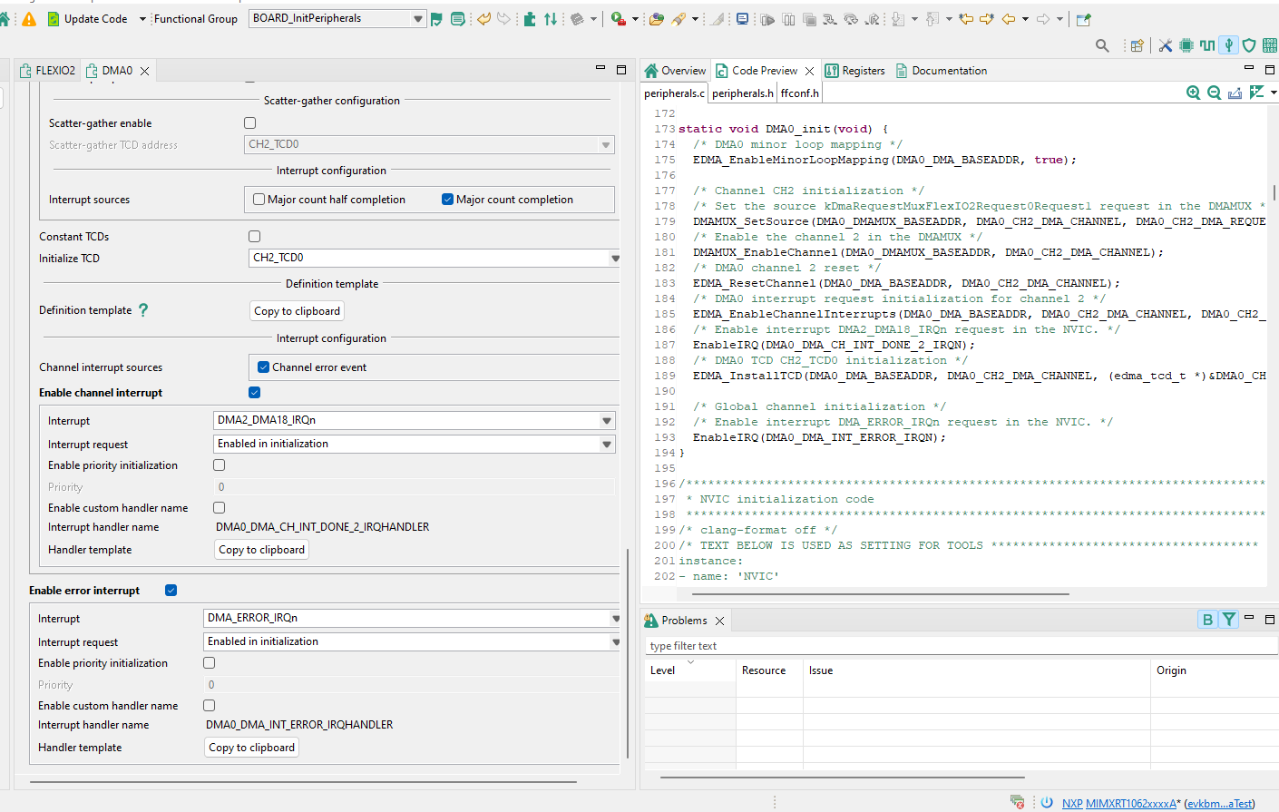
The attached images show the control setup for the FlexIO and DMA. Can you suggest what I'm doing wrong?
Many thanks!
- 新着としてマーク
- ブックマーク
- 購読
- ミュート
- RSS フィードを購読する
- ハイライト
- 印刷
- 不適切なコンテンツを報告
- 新着としてマーク
- ブックマーク
- 購読
- ミュート
- RSS フィードを購読する
- ハイライト
- 印刷
- 不適切なコンテンツを報告
There is another box that must be checked to terminate DMA when the major loop count has been reached: "Auto Stop Request"
And the source address does not automatically continue from one minor loop to the next. The minor loop offset must be set for the source (in my case) to update the original address by the number of bytes transferred in the minor loop...