
- Forums
- Product Forums
- General Purpose MicrocontrollersGeneral Purpose Microcontrollers
- i.MX Forumsi.MX Forums
- QorIQ Processing PlatformsQorIQ Processing Platforms
- Identification and SecurityIdentification and Security
- Power ManagementPower Management
- Wireless ConnectivityWireless Connectivity
- RFID / NFCRFID / NFC
- Advanced AnalogAdvanced Analog
- Neural Processing UnitsNeural Processing Units
- MCX Microcontrollers
- S32G
- S32K
- S32V
- MPC5xxx
- Other NXP Products
- S12 / MagniV Microcontrollers
- Powertrain and Electrification Analog Drivers
- Sensors
- Vybrid Processors
- Digital Signal Controllers
- 8-bit Microcontrollers
- ColdFire/68K Microcontrollers and Processors
- PowerQUICC Processors
- OSBDM and TBDML
- S32M
- S32Z/E
-
- Solution Forums
- Software Forums
- MCUXpresso Software and ToolsMCUXpresso Software and Tools
- CodeWarriorCodeWarrior
- MQX Software SolutionsMQX Software Solutions
- Model-Based Design Toolbox (MBDT)Model-Based Design Toolbox (MBDT)
- FreeMASTER
- eIQ Machine Learning Software
- Embedded Software and Tools Clinic
- S32 SDK
- S32 Design Studio
- GUI Guider
- Zephyr Project
- Voice Technology
- Application Software Packs
- Secure Provisioning SDK (SPSDK)
- Processor Expert Software
- Generative AI & LLMs
-
- Topics
- Mobile Robotics - Drones and RoversMobile Robotics - Drones and Rovers
- NXP Training ContentNXP Training Content
- University ProgramsUniversity Programs
- Rapid IoT
- NXP Designs
- SafeAssure-Community
- OSS Security & Maintenance
- Using Our Community
-
- Cloud Lab Forums
-
- Knowledge Bases
- ARM Microcontrollers
- i.MX Processors
- Identification and Security
- Model-Based Design Toolbox (MBDT)
- QorIQ Processing Platforms
- S32 Automotive Processing Platform
- Wireless Connectivity
- CodeWarrior
- MCUXpresso Suite of Software and Tools
- MQX Software Solutions
- RFID / NFC
- Advanced Analog
- Neural Processing Units
-
- NXP Tech Blogs
- Home
- :
- 汎用マイクロコントローラ
- :
- LPCマイクロコントローラ
- :
- Re: LPCX1125 yields different output on different computers
LPCX1125 yields different output on different computers
- RSS フィードを購読する
- トピックを新着としてマーク
- トピックを既読としてマーク
- このトピックを現在のユーザーにフロートします
- ブックマーク
- 購読
- ミュート
- 印刷用ページ
LPCX1125 yields different output on different computers
- 新着としてマーク
- ブックマーク
- 購読
- ミュート
- RSS フィードを購読する
- ハイライト
- 印刷
- 不適切なコンテンツを報告
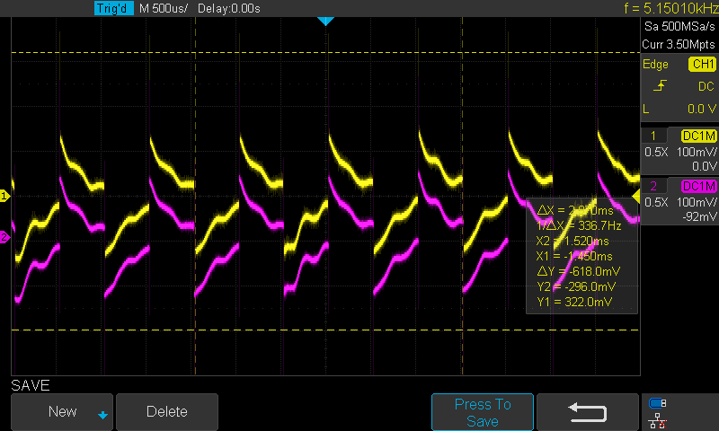
Dear community, I'm facing a weird issue on my LPCX1125 board. I'm working on a simple PWM based on 32 and 16-bit timers of the board. On my desktop PC (Win10), I'm able to debug successfully, and control/observe the corresponding digital pins based on UART (ring buffer) and an oscilloscope.
However, when I switch to my Win10 laptop with exactly same LPCXpresso ide build, the signal from the oscilloscope becomes weird, like something interfering it. I'm attaching the code and oscilloscope data (corresponding to my desktop pc -the desired one-; and from the laptop -the weird one-). Actually, I've also plugged the board on my debian-linux; monterey-mac os (with the LPCXpresso ide installed), I got the same weird signal.
I couldn't figure out the error yet. Any comments or has anyone experienced a similar problem?
- 新着としてマーク
- ブックマーク
- 購読
- ミュート
- RSS フィードを購読する
- ハイライト
- 印刷
- 不適切なコンテンツを報告
Dear frank_m, I actually tried your suggestion and updated the UART_PWM code (uart_rb.c). However, the problem remains the same. Then, I just tried the timer_PWM, which basically sets PWM using that 32 and 16-bit timers (timer_pwm.c). I think here is the problem. Once again, when I debug timer_pwm.c on my desktop PC, I'm able to set desired PWM and frequency and observe smoothly on the oscilloscope. However, when I switch to my laptop once again, it acts as the "weird signal". By the way, I observe a noise on my oscilloscope before setting the PWM to corresponding digital pins. This noise doesnt exists in my desktop PC. Any comments? Could it be related to the USB ports?
- 新着としてマーク
- ブックマーク
- 購読
- ミュート
- RSS フィードを購読する
- ハイライト
- 印刷
- 不適切なコンテンツを報告
> This noise doesnt exists in my desktop PC. Any comments? Could it be related to the USB ports?
Ground potential differences / shifts ?
And, desktop PC use to have metal casings that reduce EMI radiation.
> However, when I switch to my laptop once again, it acts as the "weird signal".
But to be clear, I see this as a mere symptom. The cause is in your firmware, I believe. Since I have neither the full code nor the hardware, I can only give pointers. (And since I am not a NXP employee, I can't spend hours on analysis).
But from browsing through your code, it seems the PWM settings are coming from the host, via serial interface. And here, individual USB host settings for the serial adapter like package size and mode do influence the UART timing. But still, I suspect the cause is in your firmware code.
I would not set the PWM cycle in a "hard" fashion in a loop, but store it and only apply in the PWM cycle interrupt. You would need to check the reference manual how the timer unit reacts upon changing settings mid-cycle.
And second, I would avoid using floating point both for calculations and for printf/scanf() calls, especially on a M0. You could do the calculation perfectly fine with integer.
And I would check what this "Chip_UART_IRQRBHandler()" is doing.
- 新着としてマーク
- ブックマーク
- 購読
- ミュート
- RSS フィードを購読する
- ハイライト
- 印刷
- 不適切なコンテンツを報告
- 新着としてマーク
- ブックマーク
- 購読
- ミュート
- RSS フィードを購読する
- ハイライト
- 印刷
- 不適切なコンテンツを報告
> ... , I'm able to debug successfully, and control/observe the corresponding digital pins based on UART (ring buffer) and an oscilloscope.
Which suggests you are UART communication within your code.
However, communication issues with USB-to-serial converters and PCs are not uncommon. They might even depend on the USB connector you plug it in, as different internal USB bridges might be involved.
Regardless of issues on the PC side, I suspect you have both the timer and the serial interrupt of your MCU firmware running on the same priority level. This can surely create jitter, inconsistencies and blockages.
I would suggest to increase the timer interrupt priority.
And under no circumstance call lengthy functions from within interrupt context, or functions that rely on other interrupts.
The "printf()" function (however it might be called in your SDK/library) is a prime example that usually violates both recommendations.
- 新着としてマーク
- ブックマーク
- 購読
- ミュート
- RSS フィードを購読する
- ハイライト
- 印刷
- 不適切なコンテンツを報告
- 新着としてマーク
- ブックマーク
- 購読
- ミュート
- RSS フィードを購読する
- ハイライト
- 印刷
- 不適切なコンテンツを報告
Assuming you don't have the most exclusive debugging tools in the 5-digits price range ...
One method to check for interrupt interference would be to toggle different GPIO pins to high at each interrupt entry, and back to low at exit.
Then you can set the scope trigger to the condition of both signals being high (if possible).