
- Forums
- Product Forums
- General Purpose MicrocontrollersGeneral Purpose Microcontrollers
- i.MX Forumsi.MX Forums
- QorIQ Processing PlatformsQorIQ Processing Platforms
- Identification and SecurityIdentification and Security
- Power ManagementPower Management
- Wireless ConnectivityWireless Connectivity
- RFID / NFCRFID / NFC
- Advanced AnalogAdvanced Analog
- Neural Processing UnitsNeural Processing Units
- MCX Microcontrollers
- S32G
- S32K
- S32V
- MPC5xxx
- Other NXP Products
- S12 / MagniV Microcontrollers
- Powertrain and Electrification Analog Drivers
- Sensors
- Vybrid Processors
- Digital Signal Controllers
- 8-bit Microcontrollers
- ColdFire/68K Microcontrollers and Processors
- PowerQUICC Processors
- OSBDM and TBDML
- S32M
- S32Z/E
-
- Solution Forums
- Software Forums
- MCUXpresso Software and ToolsMCUXpresso Software and Tools
- CodeWarriorCodeWarrior
- MQX Software SolutionsMQX Software Solutions
- Model-Based Design Toolbox (MBDT)Model-Based Design Toolbox (MBDT)
- FreeMASTER
- eIQ Machine Learning Software
- Embedded Software and Tools Clinic
- S32 SDK
- S32 Design Studio
- GUI Guider
- Zephyr Project
- Voice Technology
- Application Software Packs
- Secure Provisioning SDK (SPSDK)
- Processor Expert Software
- Generative AI & LLMs
-
- Topics
- Mobile Robotics - Drones and RoversMobile Robotics - Drones and Rovers
- NXP Training ContentNXP Training Content
- University ProgramsUniversity Programs
- Rapid IoT
- NXP Designs
- SafeAssure-Community
- OSS Security & Maintenance
- Using Our Community
-
- Cloud Lab Forums
-
- Knowledge Bases
- ARM Microcontrollers
- i.MX Processors
- Identification and Security
- Model-Based Design Toolbox (MBDT)
- QorIQ Processing Platforms
- S32 Automotive Processing Platform
- Wireless Connectivity
- CodeWarrior
- MCUXpresso Suite of Software and Tools
- MQX Software Solutions
- RFID / NFC
- Advanced Analog
- Neural Processing Units
-
- NXP Tech Blogs
- Home
- :
- General Purpose Microcontrollers
- :
- LPC Microcontrollers
- :
- LPC1788 GPIO Interrupts Slow
LPC1788 GPIO Interrupts Slow
- Subscribe to RSS Feed
- Mark Topic as New
- Mark Topic as Read
- Float this Topic for Current User
- Bookmark
- Subscribe
- Mute
- Printer Friendly Page
LPC1788 GPIO Interrupts Slow
- Mark as New
- Bookmark
- Subscribe
- Mute
- Subscribe to RSS Feed
- Permalink
- Report Inappropriate Content
I've asked this question on the Keil forums which have directed me to ask here, but i'm having some issues with interrupts on an embedded artists development board and LPC1788. I have a 1200 Hz clock coming in on a pin and I need to be able to trigger an interrupt on every falling edge, my understanding is that external interrupts should fire withing 12-16ish clock cycles, and normal GPIO interrupts may be a little bit slower. My core clock is configured to 120MHz and my peripheral clock is 60MHz, so this should be a very very small delay (~0.13 us). instead i'm seeing delays of more like 650 us and the point at which my interrupt triggers shifts relative to my input signal which it also shouldn't do.
i have tried this on both a general GPIO pin (on bank 0 or 2 as there are the supported interrupt pins) and on the EINT3 pin, with the same results.
simple example for GPIO:
#include "cmsis_os2.h"
#include "LPC177x_8x.h"
#include "GPIO_LPC17xx.h"
#include <stdio.h>

uint8_t clock_port = 0;
uint8_t clock_num = 9;
uint8_t twiddle_port = 1;
uint8_t twiddle_num = 28;

void GPIO_IRQHandler(void) {
        LPC_GPIOINT->IO0IntClr |= 1<<9;
        GPIO_PinWrite(twiddle_port, twiddle_num, 1);
        GPIO_PinWrite(twiddle_port, twiddle_num, 0);
}

int main() {
        osKernelInitialize();   // initialize CMSIS-RTOS
        SystemCoreClockUpdate();
        GPIO_PortClock(1);
        GPIO_SetDir(clock_port, clock_num, GPIO_DIR_INPUT);
        GPIO_SetDir(twiddle_port, twiddle_num, GPIO_DIR_OUTPUT);
        LPC_GPIOINT->IO0IntEnF |= 0x01 << 9; // trigger on falling edge
        NVIC_SetPriority(GPIO_IRQn, 0);         NVIC_EnableIRQ(GPIO_IRQn);
        osKernelStart ();               // start thread execution
        for (;;) { }
        return 0;
}
and for EINT3:
#include "cmsis_os2.h"
#include "LPC177x_8x.h"
#include "GPIO_LPC17xx.h"
#include <stdio.h>

uint8_t clock_port = 2;
uint8_t clock_num = 13;
uint8_t twiddle_port = 1;
uint8_t twiddle_num = 28;

void EINT3_IRQHandler(void) {
         LPC_SC->EXTINT |= 1<<3;
         GPIO_PinWrite(twiddle_port, twiddle_num, 1);
         GPIO_PinWrite(twiddle_port, twiddle_num, 0);
}

int main() {
        osKernelInitialize();   // initialize CMSIS-RTOS
        SystemCoreClockUpdate();
        GPIO_PortClock(1);
        GPIO_SetDir(clock_port, clock_num, GPIO_DIR_INPUT);
        GPIO_SetDir(twiddle_port, twiddle_num, GPIO_DIR_OUTPUT);
        LPC_SC->EXTINT = (1<<3);           /* Clear Pending interrupts */
        LPC_IOCON->P2_13 = 1;
        LPC_SC->EXTMODE = (1<<3);  /* Configure EINTx as Edge Triggered*/
        LPC_SC->EXTPOLAR = (1<<3); /* Configure EINTx as Falling Edge */
        NVIC_SetPriority(EINT3_IRQn, 0);
        NVIC_EnableIRQ(EINT3_IRQn);
        osKernelStart ();               // start thread execution
        for (;;) { }
        return 0;
}
the GPIO pinwrite function is:
void GPIO_PinWrite (uint32_t port_num, uint32_t pin_num, uint32_t val) {
    val ? (LPC_GPIO(port_num)->SET = (1UL << pin_num)) : \
          (LPC_GPIO(port_num)->CLR = (1UL << pin_num));
}
and I have also tried with a toggle logic in the interrupt with the same results.
I'm using keil uvision 5.28a, with cmsis V2 using RTX5 as the underlying RTOS
Am I missing something in the setup?
- Mark as New
- Bookmark
- Subscribe
- Mute
- Subscribe to RSS Feed
- Permalink
- Report Inappropriate Content
Hi James Kent ,
Thanks for your reply.
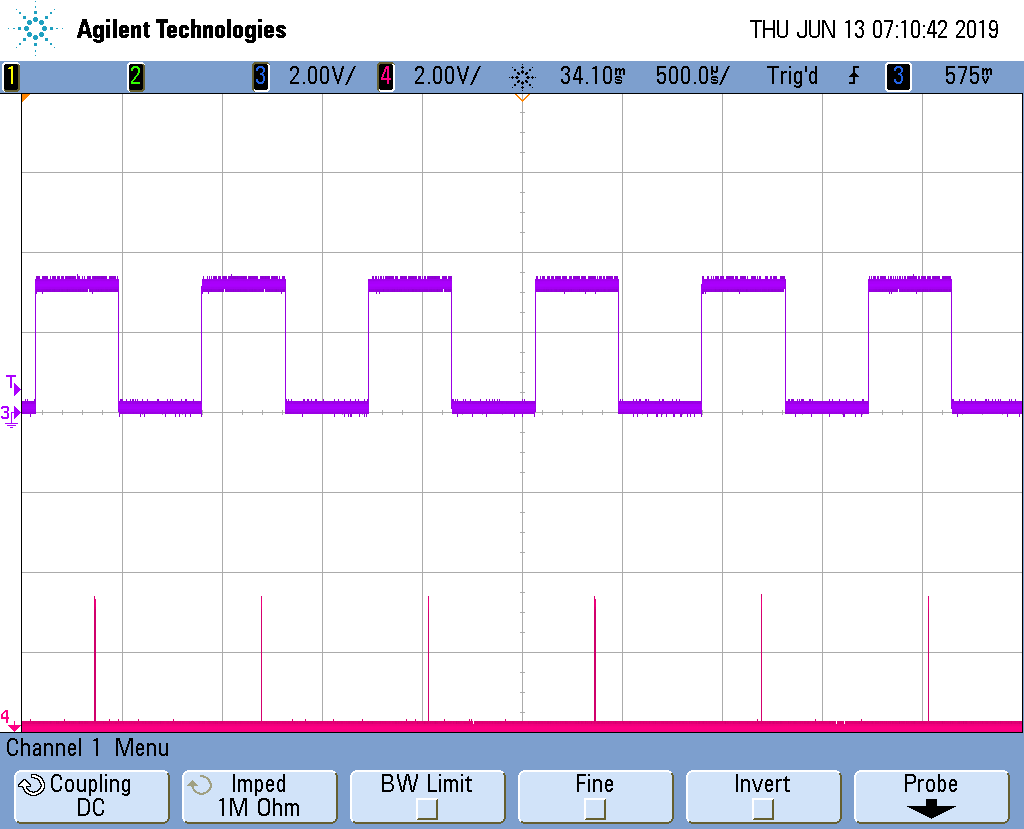
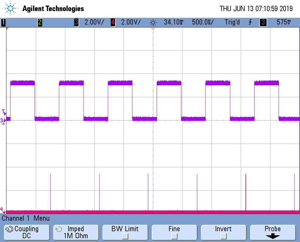
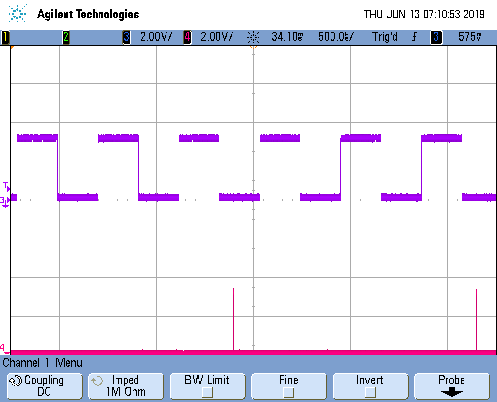
I'd like to run the periph_timer demo which is from the LPCOpen library to replicate the phenomenon you mentioned, the P0.21 outputs the 1.2 KHz PWM, then connect the PWM to the P2.10, it will trigger an interrupt when detecting the falling edge, and in the GPIO interrupt function, it toggles the P0.22.
After running the demo on the LPC1788 Eva board, I find that the delay is about 1.8 us which much smaller than 650 us, and I think it still can decrease with some tricks.
I've attached my testing code, please check it.

Fig 1

Fig 2
Have a great day,
TIC
-------------------------------------------------------------------------------
Note:
- If this post answers your question, please click the "Mark Correct" button. Thank you!
- We are following threads for 7 weeks after the last post, later replies are ignored
Please open a new thread and refer to the closed one, if you have a related question at a later point in time.
-------------------------------------------------------------------------------
- Mark as New
- Bookmark
- Subscribe
- Mute
- Subscribe to RSS Feed
- Permalink
- Report Inappropriate Content
Thanks for the help in this, it looks like i didn't have the repetitive interrupt timer enabled in PCONP, once enabled i am now getting the expected timings of ~1uS from trigger to interrupt.
- Mark as New
- Bookmark
- Subscribe
- Mute
- Subscribe to RSS Feed
- Permalink
- Report Inappropriate Content
Hi jeremyzhou, it is the delay between the input signal and the output pulse, however this is on the order of 650 uS, and it "moves" over time relative to the trigger, as hopefully my screenshots show. i have tried what you suggested and it made no difference at all.
- Mark as New
- Bookmark
- Subscribe
- Mute
- Subscribe to RSS Feed
- Permalink
- Report Inappropriate Content
Hi James Kent ,
Thanks for your reply.
Thanks for your reply.
I was wondering if you can share a compilable demo which can replicate the phenomenon, looking forward to your reply.
Have a great day,
TIC
-------------------------------------------------------------------------------
Note:
- If this post answers your question, please click the "Mark Correct" button. Thank you!
- We are following threads for 7 weeks after the last post, later replies are ignored
Please open a new thread and refer to the closed one, if you have a related question at a later point in time.
-------------------------------------------------------------------------------
- Mark as New
- Bookmark
- Subscribe
- Mute
- Subscribe to RSS Feed
- Permalink
- Report Inappropriate Content
I have attached a zip file with a simple project that exhibits this problem, my input signal is a 1200Hz clock with a 50Hz duty cycle.
- Mark as New
- Bookmark
- Subscribe
- Mute
- Subscribe to RSS Feed
- Permalink
- Report Inappropriate Content
Hi James Kent ,
Thank you for your interest in NXP Semiconductor products and
for the opportunity to serve you.
According to your statement, the 'delay' you mentioned is the interval between the input clock and GPIO pulse which is triggered in the interrupt function, is it right?
If yes, I'd like to suggest you set the SLEW bit in the corresponding IOCON register, it can reduce the output delay.
Hope it helps.
Have a great day,
TIC

-------------------------------------------------------------------------------
Note:
- If this post answers your question, please click the "Mark Correct" button. Thank you!
- We are following threads for 7 weeks after the last post, later replies are ignored
Please open a new thread and refer to the closed one, if you have a related question at a later point in time.
-------------------------------------------------------------------------------