
- Forums
- Product Forums
- General Purpose MicrocontrollersGeneral Purpose Microcontrollers
- i.MX Forumsi.MX Forums
- QorIQ Processing PlatformsQorIQ Processing Platforms
- Identification and SecurityIdentification and Security
- Power ManagementPower Management
- Wireless ConnectivityWireless Connectivity
- RFID / NFCRFID / NFC
- Advanced AnalogAdvanced Analog
- Neural Processing UnitsNeural Processing Units
- MCX Microcontrollers
- S32G
- S32K
- S32V
- MPC5xxx
- Other NXP Products
- S12 / MagniV Microcontrollers
- Powertrain and Electrification Analog Drivers
- Sensors
- Vybrid Processors
- Digital Signal Controllers
- 8-bit Microcontrollers
- ColdFire/68K Microcontrollers and Processors
- PowerQUICC Processors
- OSBDM and TBDML
- S32M
- S32Z/E
-
- Solution Forums
- Software Forums
- MCUXpresso Software and ToolsMCUXpresso Software and Tools
- CodeWarriorCodeWarrior
- MQX Software SolutionsMQX Software Solutions
- Model-Based Design Toolbox (MBDT)Model-Based Design Toolbox (MBDT)
- FreeMASTER
- eIQ Machine Learning Software
- Embedded Software and Tools Clinic
- S32 SDK
- S32 Design Studio
- GUI Guider
- Zephyr Project
- Voice Technology
- Application Software Packs
- Secure Provisioning SDK (SPSDK)
- Processor Expert Software
- Generative AI & LLMs
-
- Topics
- Mobile Robotics - Drones and RoversMobile Robotics - Drones and Rovers
- NXP Training ContentNXP Training Content
- University ProgramsUniversity Programs
- Rapid IoT
- NXP Designs
- SafeAssure-Community
- OSS Security & Maintenance
- Using Our Community
-
- Cloud Lab Forums
-
- Knowledge Bases
- ARM Microcontrollers
- i.MX Processors
- Identification and Security
- Model-Based Design Toolbox (MBDT)
- QorIQ Processing Platforms
- S32 Automotive Processing Platform
- Wireless Connectivity
- CodeWarrior
- MCUXpresso Suite of Software and Tools
- MQX Software Solutions
- RFID / NFC
- Advanced Analog
- Neural Processing Units
-
- NXP Tech Blogs
- Home
- :
- General Purpose Microcontrollers
- :
- Kinetis Microcontrollers
- :
- Quadrature Decoder not counting correctly on FRDM-K66F
Quadrature Decoder not counting correctly on FRDM-K66F
- Subscribe to RSS Feed
- Mark Topic as New
- Mark Topic as Read
- Float this Topic for Current User
- Bookmark
- Subscribe
- Mute
- Printer Friendly Page
- Mark as New
- Bookmark
- Subscribe
- Mute
- Subscribe to RSS Feed
- Permalink
- Report Inappropriate Content
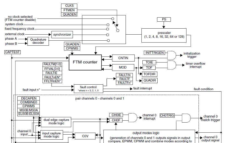
I have FRDM-K66F and using a CUI inc Encoder AMT213B-V that has 1024 PPR (pulse per revolution) and I have it connected to FTM1 on FRDM board. (because I also need CAN0 that shares I/O pins with FTM2 on PTB18,PTB19. So I used MCUExpresso Config Tool to set up the FTM1 pins, and registers,
I run example code from Quadrature Encode/Decode example in SDK for FRDM-K66F that uses PIT timer to do a once per second read of the count register of FTM. This example manually does some setting up of FTM so I comment this out and use the BOARD_InitPeripherals(), BOARD_InitPins(); BOARD_BootClockRUN(); BOARD_InitDebugConsole()
to set up all the registers at boot time.
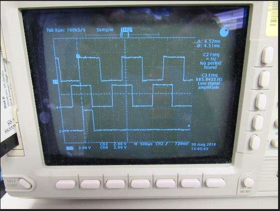
I have viewed the encoder output and the signals look just fine with A and B signals 90Degrees out of phase with each other and signal is solid 3.3V ( encoder outputs 5v signal that goes through a 5v to 3.3v voltage translator.)
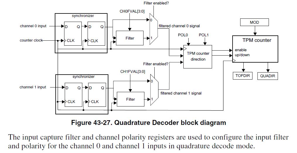
when I spin the encoder one full revolution, i should get 4096 Edges counted. (for both rising and falling edges on both A and B as per manual page 1254 of K66 Sub Family Reference Manual Rev 2 May 2015
I spin the encoder at a slow rate about one revolution per 1/2 second. and I Measure around 3800 PPR in both + and - directions. So this tells me one of three possibilities.
1) The encoder puts out less PPR than stated.
2) the Quadrature Decoder is not working / counting properly
3) The settings for FTM are not correct causing #2 above
See attachment. Clock settings are Core clock 120MHz, System clock 120MHz, Bus Clock 60MHz, OSCERCLK 12MHz
I have tried Input filter settings of 1 to 12 on both channels A and B and the number does not seem to change the 3800PPR I am seeing.
Does anyone have and suggestions on how to fix?
Solved! Go to Solution.
- Mark as New
- Bookmark
- Subscribe
- Mute
- Subscribe to RSS Feed
- Permalink
- Report Inappropriate Content
I wrote a program to output encoder signals on PTD12 and PTD13 on the FREEDOM board to eliminate any possibility of bad voltage or noise signals from a physical encoder, i input these into FTM1 phase A and B, and run program. Turns OUT that the SemiHosting Debugging is causing the errors. it completely stops the processor and interrupts during "Console Talking" and is the reason for the errors. If program is run without debug console it works as intended.
- Mark as New
- Bookmark
- Subscribe
- Mute
- Subscribe to RSS Feed
- Permalink
- Report Inappropriate Content
Hi, Jeff,
Regarding the decoder for FRDM-K66F, I think the example code is fine, the encoder sensor hardware is fine, the difference between the expected counting and the actual counting is the position error you spins the rotor manually.
I suggest you do not read the FTM counter in PIT ISR. After You start counting, you can spin the rotor multiple revolutions for example 10 revolutions, then in the debugger, break the code and read the FTM counter, in this way, the accumulative error can be reduced by average.
Hope it can help you
BR
Xiangjun Rong
- Mark as New
- Bookmark
- Subscribe
- Mute
- Subscribe to RSS Feed
- Permalink
- Report Inappropriate Content
I have got this response from filing a tech support ticket: It has some good advise on how to debug, and other ways to try to do comparison testing. so I will post this here for others to read. however it still misses the main point that I already know that the encoder outputs 1024 PPR pulse per revolution. I suspect that some how in firmware the registers are not set up or have some kind of conflict? I have attached a COPAL RE30E1024-213 -1 Encoder to FRDM-K66F devboard at FTM1 pins PTA8 and PTA9. I get very stable Encoder pulse signal.
| Dear Jeff Sylvester, |
Regarding your question, it is difficult to make a conclusion that the code or Decoder hardware has issue. The key is that you have to know how many pulses has been generated by the Encoder after you spin the rotor manually. In order to know pusle number the encoder generates, I think you can use capture function of FTM, in detail, you can connect one Encoder signal(PhaseA or PhaseB, not both) to FTM2_CHx, configure the channel of FTM2 in capture mode to generate capture interrupt with rising edge , in the capture ISR, you can increase a variable by 1, in this way, you can know how many pulses has been generated, then you can compare the quadrature counter and the pulse variable and check if they match or not. Another method is that you connect the PhaseA for example to LPTMR_ALT1(PTC5), then configure theLPTMR to count the pulse rising edge, then compare the LPTMR counter and the quadrature counter. Hope it can help you To update this case, please reply to this email. Thank you for your interest in NXP Semiconductor products and for the opportunity to serve you. Best regards, X.j. Technical Support NXP Semiconductor |
- Mark as New
- Bookmark
- Subscribe
- Mute
- Subscribe to RSS Feed
- Permalink
- Report Inappropriate Content
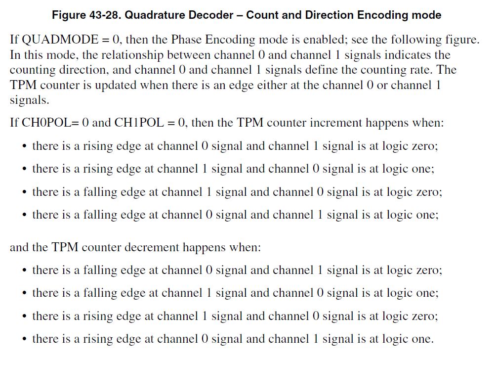
Status Update. If I connect a signal generator signal 0 to 3.3V square wave running at 1000Hz on to the Freedom board Phase A pin with Phase B pin pulled up to 3.3v or down to GND with a resistor, and switch FTM Quadrature Decoder Mode from Phase A and Phase B encoding mode TO Count and Direction encoding mode, I get a count of +250 or -250 depending on the logic value on Phase B pin.