
- Forums
- Product Forums
- General Purpose MicrocontrollersGeneral Purpose Microcontrollers
- i.MX Forumsi.MX Forums
- QorIQ Processing PlatformsQorIQ Processing Platforms
- Identification and SecurityIdentification and Security
- Power ManagementPower Management
- Wireless ConnectivityWireless Connectivity
- RFID / NFCRFID / NFC
- Advanced AnalogAdvanced Analog
- Neural Processing UnitsNeural Processing Units
- MCX Microcontrollers
- S32G
- S32K
- S32V
- MPC5xxx
- Other NXP Products
- S12 / MagniV Microcontrollers
- Powertrain and Electrification Analog Drivers
- Sensors
- Vybrid Processors
- Digital Signal Controllers
- 8-bit Microcontrollers
- ColdFire/68K Microcontrollers and Processors
- PowerQUICC Processors
- OSBDM and TBDML
- S32M
- S32Z/E
-
- Solution Forums
- Software Forums
- MCUXpresso Software and ToolsMCUXpresso Software and Tools
- CodeWarriorCodeWarrior
- MQX Software SolutionsMQX Software Solutions
- Model-Based Design Toolbox (MBDT)Model-Based Design Toolbox (MBDT)
- FreeMASTER
- eIQ Machine Learning Software
- Embedded Software and Tools Clinic
- S32 SDK
- S32 Design Studio
- GUI Guider
- Zephyr Project
- Voice Technology
- Application Software Packs
- Secure Provisioning SDK (SPSDK)
- Processor Expert Software
- Generative AI & LLMs
-
- Topics
- Mobile Robotics - Drones and RoversMobile Robotics - Drones and Rovers
- NXP Training ContentNXP Training Content
- University ProgramsUniversity Programs
- Rapid IoT
- NXP Designs
- SafeAssure-Community
- OSS Security & Maintenance
- Using Our Community
-
- Cloud Lab Forums
-
- Knowledge Bases
- ARM Microcontrollers
- i.MX Processors
- Identification and Security
- Model-Based Design Toolbox (MBDT)
- QorIQ Processing Platforms
- S32 Automotive Processing Platform
- Wireless Connectivity
- CodeWarrior
- MCUXpresso Suite of Software and Tools
- MQX Software Solutions
- RFID / NFC
- Advanced Analog
- Neural Processing Units
-
- NXP Tech Blogs
- Home
- :
- General Purpose Microcontrollers
- :
- Kinetis Microcontrollers
- :
- K60 FTM - PWM Combine - Adjust CnV whilst running...
K60 FTM - PWM Combine - Adjust CnV whilst running...
- Subscribe to RSS Feed
- Mark Topic as New
- Mark Topic as Read
- Float this Topic for Current User
- Bookmark
- Subscribe
- Mute
- Printer Friendly Page
K60 FTM - PWM Combine - Adjust CnV whilst running...

- Mark as New
- Bookmark
- Subscribe
- Mute
- Subscribe to RSS Feed
- Permalink
- Report Inappropriate Content
I am not trying to generate a PWM signal, but rather some related pulses to quite fast timings (uS / nS) and the FTM seems to be the most suitable peripheral to do it.
I am running the channels in PWM Combine mode, so (for instance) I have a pin assigned to FT0_CH0; on FTM_CNT == FT0C0V the pin is taken HIGH, and on FTM_CNT == FT0C1V the pin is taken low again.
CH2, 4, & 6 are set similarly in order to give me a set of related signals.
This works well, but after the initial pulses on CH0 and CH6 a need to generate a second pulse of a different width.
The required output can be visualized thus:
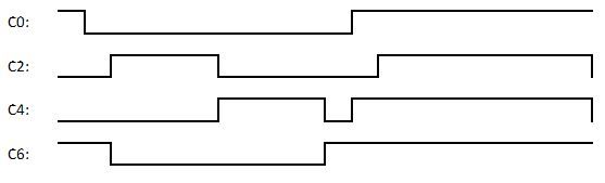
Due to the way I am using the module I do not leave it running indefinitely, rather I start it at the begin of one of the above cycles, and stop it at the end.
What is the best way for me to load the new C2V/C3V and C4V/C5V values into the FMT module whilst the timer is running?
I can get close to what I need if I interrupt on the falling edge of the C4 signal (so actually on the C5 event), stop the timer, reset CNT to zero, set new values into the timer, and restart it again, but this seems to take quite some time (comparatively speaking), in the order of a few microseconds.
Bizarrely, if use the same interrupt, stop the timer (but don't reset CNT), set up the new pulses to appropriate values (that are in excess of the current CNT value) and restart it the second set of pulses on C0 and C2 never seem to get generated, I am not sure why this is? Can the FTM only trigger one per channel (prior to an overflow?) - I don't see anything documented to this effect?
Thanks for any pointers in the right direction!
- Mark as New
- Bookmark
- Subscribe
- Mute
- Subscribe to RSS Feed
- Permalink
- Report Inappropriate Content
Ok, so I've stripped this back to be much simplier.
Using just channels 2 & 3 I am trying to create a 10us pulse, a 10us gap, and then a 20us pulse on the CH2 output pin:

Due to my "end goal" I don't want to stop the timer after the first pulse, or reset the CNT value, I just want to force load the C2V and C3V registers from the buffers with new values.
Channels 2 & 3 are set to "Combine PWM", and I've enabled synchronisation (SYNCEN1 in FTM0_COMIBINE register) believing that doing so will mean that the CnV registers for this channel pair will be included when I perform my software sync.
Processor Expert has generated the following "init" code, based on the settings:
/*
** ===================================================================
** Method : FT0_Init (component Init_FTM)
**
** Description :
** This method initializes registers of the FTM module
** according to the Peripheral Initialization settings.
** Call this method in user code to initialize the module. By
** default, the method is called by PE automatically; see "Call
** Init method" property of the component for more details.
** Parameters : None
** Returns : Nothing
** ===================================================================
*/
void FT0_Init(void)
{
/* SIM_SCGC6: FTM0=1 */
SIM_SCGC6 |= (uint32_t)0x01000000UL;
(void)(FTM0_SC == 0U); /* Dummy read of the FTM0_SC register to clear the interrupt flag */
/* FTM0_SC: ??=0,??=0,??=0,??=0,??=0,??=0,??=0,??=0,??=0,??=0,??=0,??=0,??=0,??=0,??=0,??=0,??=0,??=0,??=0,??=0,??=0,??=0,??=0,??=0,TOF=0,TOIE=0,CPWMS=0,CLKS=0,PS=0 */
FTM0_SC = (uint32_t)0x00UL; /* Stop the counter */
(void)(FTM0_C2SC == 0U); /* Dummy read of the FTM0_C2SC register to clear the interrupt flag */
(void)(FTM0_C3SC == 0U); /* Dummy read of the FTM0_C3SC register to clear the interrupt flag */
/* FTM0_C0SC: ??=0,??=0,??=0,??=0,??=0,??=0,??=0,??=0,??=0,??=0,??=0,??=0,??=0,??=0,??=0,??=0,??=0,??=0,??=0,??=0,??=0,??=0,??=0,??=0,CHF=0,CHIE=0,MSB=0,MSA=0,ELSB=0,ELSA=0,??=0,DMA=0 */
FTM0_C0SC = (uint32_t)0x00UL;
/* FTM0_C1SC: ??=0,??=0,??=0,??=0,??=0,??=0,??=0,??=0,??=0,??=0,??=0,??=0,??=0,??=0,??=0,??=0,??=0,??=0,??=0,??=0,??=0,??=0,??=0,??=0,CHF=0,CHIE=0,MSB=0,MSA=0,ELSB=0,ELSA=0,??=0,DMA=0 */
FTM0_C1SC = (uint32_t)0x00UL;
/* FTM0_C2SC: ??=0,??=0,??=0,??=0,??=0,??=0,??=0,??=0,??=0,??=0,??=0,??=0,??=0,??=0,??=0,??=0,??=0,??=0,??=0,??=0,??=0,??=0,??=0,??=0,CHF=0,CHIE=0,MSB=0,MSA=0,ELSB=0,ELSA=0,??=0,DMA=0 */
FTM0_C2SC = (uint32_t)0x00UL;
/* FTM0_C3SC: ??=0,??=0,??=0,??=0,??=0,??=0,??=0,??=0,??=0,??=0,??=0,??=0,??=0,??=0,??=0,??=0,??=0,??=0,??=0,??=0,??=0,??=0,??=0,??=0,CHF=0,CHIE=0,MSB=0,MSA=0,ELSB=0,ELSA=0,??=0,DMA=0 */
FTM0_C3SC = (uint32_t)0x00UL;
/* FTM0_C4SC: ??=0,??=0,??=0,??=0,??=0,??=0,??=0,??=0,??=0,??=0,??=0,??=0,??=0,??=0,??=0,??=0,??=0,??=0,??=0,??=0,??=0,??=0,??=0,??=0,CHF=0,CHIE=0,MSB=0,MSA=0,ELSB=0,ELSA=0,??=0,DMA=0 */
FTM0_C4SC = (uint32_t)0x00UL;
/* FTM0_C5SC: ??=0,??=0,??=0,??=0,??=0,??=0,??=0,??=0,??=0,??=0,??=0,??=0,??=0,??=0,??=0,??=0,??=0,??=0,??=0,??=0,??=0,??=0,??=0,??=0,CHF=0,CHIE=0,MSB=0,MSA=0,ELSB=0,ELSA=0,??=0,DMA=0 */
FTM0_C5SC = (uint32_t)0x00UL;
/* FTM0_C6SC: ??=0,??=0,??=0,??=0,??=0,??=0,??=0,??=0,??=0,??=0,??=0,??=0,??=0,??=0,??=0,??=0,??=0,??=0,??=0,??=0,??=0,??=0,??=0,??=0,CHF=0,CHIE=0,MSB=0,MSA=0,ELSB=0,ELSA=0,??=0,DMA=0 */
FTM0_C6SC = (uint32_t)0x00UL;
/* FTM0_C7SC: ??=0,??=0,??=0,??=0,??=0,??=0,??=0,??=0,??=0,??=0,??=0,??=0,??=0,??=0,??=0,??=0,??=0,??=0,??=0,??=0,??=0,??=0,??=0,??=0,CHF=0,CHIE=0,MSB=0,MSA=0,ELSB=0,ELSA=0,??=0,DMA=0 */
FTM0_C7SC = (uint32_t)0x00UL;
/* FTM0_SC: TOF=0,CPWMS=0 */
FTM0_SC &= (uint32_t)~0xA0UL;
/* FTM0_MODE: WPDIS=1 */
FTM0_MODE |= (uint32_t)0x04UL; /* Disable write protection */
/* FTM0_MODE: FTMEN=1 */
FTM0_MODE |= (uint32_t)0x01UL;
/* FTM0_COMBINE: FAULTEN3=0,SYNCEN3=0,DTEN3=0,COMP3=0,FAULTEN2=0,SYNCEN2=1,DTEN2=0,COMP2=0,FAULTEN1=0,SYNCEN1=1,DTEN1=0,DECAPEN1=0,COMP1=0,COMBINE1=1,FAULTEN0=0,SYNCEN0=0,DTEN0=0,COMP0=0 */
FTM0_COMBINE = (uint32_t)((FTM0_COMBINE & (uint32_t)~0x72525672UL) | (uint32_t)0x00202100UL);
/* FTM0_INVCTRL: INV3EN=0,INV2EN=0,INV1EN=0,INV0EN=0 */
FTM0_INVCTRL &= (uint32_t)~0x0FUL;
/* FTM0_C0SC: ??=0,??=0,??=0,??=0,??=0,??=0,??=0,??=0,??=0,??=0,??=0,??=0,??=0,??=0,??=0,??=0,??=0,??=0,??=0,??=0,??=0,??=0,??=0,??=0,CHF=0,MSB=0,MSA=0,ELSB=0,ELSA=0,??=0 */
FTM0_C0SC &= (uint32_t)~0xFFFFFFBEUL;
/* FTM0_C1SC: ??=0,??=0,??=0,??=0,??=0,??=0,??=0,??=0,??=0,??=0,??=0,??=0,??=0,??=0,??=0,??=0,??=0,??=0,??=0,??=0,??=0,??=0,??=0,??=0,CHF=0,MSB=0,MSA=0,ELSB=0,ELSA=0,??=0 */
FTM0_C1SC &= (uint32_t)~0xFFFFFFBEUL;
/* FTM0_C2SC: ??=0,??=0,??=0,??=0,??=0,??=0,??=0,??=0,??=0,??=0,??=0,??=0,??=0,??=0,??=0,??=0,??=0,??=0,??=0,??=0,??=0,??=0,??=0,??=0,CHF=0,CHIE=0,ELSB=1,ELSA=0,??=0,DMA=0 */
FTM0_C2SC = (uint32_t)((FTM0_C2SC & (uint32_t)~0xFFFFFFC7UL) | (uint32_t)0x08UL);
/* FTM0_C3SC: ??=0,??=0,??=0,??=0,??=0,??=0,??=0,??=0,??=0,??=0,??=0,??=0,??=0,??=0,??=0,??=0,??=0,??=0,??=0,??=0,??=0,??=0,??=0,??=0,CHF=0,CHIE=1,ELSB=1,ELSA=0,??=0,DMA=0 */
FTM0_C3SC = (uint32_t)((FTM0_C3SC & (uint32_t)~0xFFFFFF87UL) | (uint32_t)0x48UL);
/* FTM0_C4SC: ??=0,??=0,??=0,??=0,??=0,??=0,??=0,??=0,??=0,??=0,??=0,??=0,??=0,??=0,??=0,??=0,??=0,??=0,??=0,??=0,??=0,??=0,??=0,??=0,CHF=0,MSB=0,MSA=0,ELSB=0,ELSA=0,??=0 */
FTM0_C4SC &= (uint32_t)~0xFFFFFFBEUL;
/* FTM0_C5SC: ??=0,??=0,??=0,??=0,??=0,??=0,??=0,??=0,??=0,??=0,??=0,??=0,??=0,??=0,??=0,??=0,??=0,??=0,??=0,??=0,??=0,??=0,??=0,??=0,CHF=0,MSB=0,MSA=0,ELSB=0,ELSA=0,??=0 */
FTM0_C5SC &= (uint32_t)~0xFFFFFFBEUL;
/* FTM0_C6SC: ??=0,??=0,??=0,??=0,??=0,??=0,??=0,??=0,??=0,??=0,??=0,??=0,??=0,??=0,??=0,??=0,??=0,??=0,??=0,??=0,??=0,??=0,??=0,??=0,CHF=0,MSB=0,MSA=0,ELSB=0,ELSA=0,??=0 */
FTM0_C6SC &= (uint32_t)~0xFFFFFFBEUL;
/* FTM0_C7SC: ??=0,??=0,??=0,??=0,??=0,??=0,??=0,??=0,??=0,??=0,??=0,??=0,??=0,??=0,??=0,??=0,??=0,??=0,??=0,??=0,??=0,??=0,??=0,??=0,CHF=0,MSB=0,MSA=0,ELSB=0,ELSA=0,??=0 */
FTM0_C7SC &= (uint32_t)~0xFFFFFFBEUL;
/* FTM0_C2V: ??=0,??=0,??=0,??=0,??=0,??=0,??=0,??=0,??=0,??=0,??=0,??=0,??=0,??=0,??=0,??=0,VAL=0xDEAD */
FTM0_C2V = (uint32_t)0xDEADUL;
/* FTM0_C3V: ??=0,??=0,??=0,??=0,??=0,??=0,??=0,??=0,??=0,??=0,??=0,??=0,??=0,??=0,??=0,??=0,VAL=0xBEEF */
FTM0_C3V = (uint32_t)0xBEEFUL;
/* FTM0_POL: POL3=0,POL2=0 */
FTM0_POL &= (uint32_t)~0x0CUL;
/* FTM0_FILTER: CH3FVAL=0,CH2FVAL=0 */
FTM0_FILTER &= (uint32_t)~0xFF00UL;
/* FTM0_OUTINIT: ??=0,??=0,??=0,??=0,??=0,??=0,??=0,??=0,??=0,??=0,??=0,??=0,??=0,??=0,??=0,??=0,??=0,??=0,??=0,??=0,??=0,??=0,??=0,??=0,CH3OI=0,CH2OI=0 */
FTM0_OUTINIT &= (uint32_t)~0xFFFFFF0CUL;
/* FTM0_OUTMASK: CH3OM=0,CH2OM=0 */
FTM0_OUTMASK &= (uint32_t)~0x0CUL;
/* FTM0_FLTCTRL: FFVAL=0 */
FTM0_FLTCTRL &= (uint32_t)~0x0F00UL;
/* FTM0_FLTPOL: FLT3POL=0,FLT2POL=0,FLT1POL=0,FLT0POL=0 */
FTM0_FLTPOL &= (uint32_t)~0x0FUL;
/* FTM0_FLTCTRL: FFLTR3EN=0,FFLTR2EN=0,FFLTR1EN=0,FFLTR0EN=0,FAULT3EN=0,FAULT2EN=0,FAULT1EN=0,FAULT0EN=0 */
FTM0_FLTCTRL &= (uint32_t)~0xFFUL;
/* FTM0_SYNC: SWSYNC=0,TRIG2=0,TRIG1=0,TRIG0=0,SYNCHOM=0,CNTMAX=0,CNTMIN=0 */
FTM0_SYNC &= (uint32_t)~0xFBUL;
/* FTM0_EXTTRIG: INITTRIGEN=0,CH1TRIG=0,CH0TRIG=0,CH5TRIG=0,CH4TRIG=0,CH3TRIG=0,CH2TRIG=0 */
FTM0_EXTTRIG &= (uint32_t)~0x7FUL;
/* FTM0_MOD: MOD=0xFFFF */
FTM0_MOD |= (uint32_t)0xFFFFUL;
/* FTM0_CNTIN: INIT=0 */
FTM0_CNTIN &= (uint32_t)~0xFFFFUL;
/* FTM0_DEADTIME: DTPS=0,DTVAL=0 */
FTM0_DEADTIME &= (uint32_t)~0xFFUL;
/* FTM0_CNT: COUNT=0 */
FTM0_CNT &= (uint32_t)~0xFFFFUL;
/* FTM0_MODE: ??=0,??=0,??=0,??=0,??=0,??=0,??=0,??=0,??=0,??=0,??=0,??=0,??=0,??=0,??=0,??=0,??=0,??=0,??=0,??=0,??=0,??=0,??=0,??=0,FAULTIE=0,FAULTM=0,PWMSYNC=0,INIT=1,FTMEN=1 */
FTM0_MODE = (uint32_t)((FTM0_MODE & (uint32_t)~0xFFFFFFE8UL) | (uint32_t)0x03UL);
/* FTM0_SYNCONF: ??=0,??=0,??=0,??=0,??=0,??=0,??=0,??=0,??=0,??=0,??=0,HWSOC=0,HWINVC=0,HWOM=0,HWWRBUF=0,HWRSTCNT=0,??=0,??=0,??=0,SWSOC=0,SWINVC=0,SWOM=0,SWWRBUF=1,SWRSTCNT=0,SYNCMODE=1,??=0,SWOC=0,INVC=0,??=0,CNTINC=0,??=0,HWTRIGMODE=1 */
FTM0_SYNCONF = (uint32_t)0x0281UL;
/* FTM0_SC: TOF=0,TOIE=0,CPWMS=0,CLKS=0,PS=0 */
FTM0_SC &= (uint32_t)~0xFFUL;
/* FTM0_FMS: FAULTF=0,WPEN=0,FAULTF3=0,FAULTF2=0,FAULTF1=0,FAULTF0=0 */
FTM0_FMS &= (uint32_t)~0xCFUL;
/* FTM0_SWOCTRL: CH3OC=0,CH2OC=0 */
FTM0_SWOCTRL &= (uint32_t)~0x0CUL;
/* FTM0_CONF: GTBEOUT=0,GTBEEN=0,BDMMODE=0,NUMTOF=0 */
FTM0_CONF &= (uint32_t)~0x06DFUL;
/* FTM0_PWMLOAD: LDOK=0,CH7SEL=0,CH6SEL=0,CH5SEL=0,CH4SEL=0,CH3SEL=0,CH2SEL=0,CH1SEL=0,CH0SEL=0 */
FTM0_PWMLOAD &= (uint32_t)~0x02FFUL;
}The relevant sections for syncing (as I understand it all look ok to me):
FTMEN is set, and the SYNCEN bits are set for channel group 1:
/* FTM0_MODE: FTMEN=1 */
FTM0_MODE |= (uint32_t)0x01UL;
/* FTM0_COMBINE: FAULTEN3=0,SYNCEN3=0,DTEN3=0,COMP3=0,FAULTEN2=0,SYNCEN2=1,DTEN2=0,COMP2=0,FAULTEN1=0,SYNCEN1=1,DTEN1=0,DECAPEN1=0,COMP1=0,COMBINE1=1,FAULTEN0=0,SYNCEN0=0,DTEN0=0,COMP0=0 */
FTM0_COMBINE = (uint32_t)((FTM0_COMBINE & (uint32_t)~0x72525672UL) | (uint32_t)0x00202100UL);SYNCMODE is 1, and SWWRBUF is also 1 (so that the CnV registers will be updated on the trigger:
/* FTM0_MODE: ??=0,??=0,??=0,??=0,??=0,??=0,??=0,??=0,??=0,??=0,??=0,??=0,??=0,??=0,??=0,??=0,??=0,??=0,??=0,??=0,??=0,??=0,??=0,??=0,FAULTIE=0,FAULTM=0,PWMSYNC=0,INIT=1,FTMEN=1 */
FTM0_MODE = (uint32_t)((FTM0_MODE & (uint32_t)~0xFFFFFFE8UL) | (uint32_t)0x03UL);
/* FTM0_SYNCONF: ??=0,??=0,??=0,??=0,??=0,??=0,??=0,??=0,??=0,??=0,??=0,HWSOC=0,HWINVC=0,HWOM=0,HWWRBUF=0,HWRSTCNT=0,??=0,??=0,??=0,SWSOC=0,SWINVC=0,SWOM=0,SWWRBUF=1,SWRSTCNT=0,SYNCMODE=1,??=0,SWOC=0,INVC=0,??=0,CNTINC=0,??=0,HWTRIGMODE=1 */
FTM0_SYNCONF = (uint32_t)0x0281UL; Unless I am missing something?
The K60 reference Manual has this to say regarding C(n)V and C(n+1)V register synchronization:
40.4.11.6 C(n)V and C(n+1)V register synchronization
The C(n)V and C(n+1)V registers synchronization updates the C(n)V and C(n+1)V registers with their buffer values.
This synchronization is enabled if (FTMEN = 1) and (SYNCEN = 1). The synchronization mechanism is the same as the MOD register synchronization.However, it is expected that the C(n)V and C(n+1)V registers be synchronized only by the enhanced PWM synchronization (SYNCMODE = 1).
and the reference MOD section:
40.4.11.4 MOD register synchronization
The MOD register synchronization updates the MOD register with its buffer value.This synchronization is enabled if (FTMEN = 1).
The MOD register synchronization can be done by either the enhanced PWM synchronization (SYNCMODE = 1) or the legacy PWM synchronization (SYNCMODE = 0). However, it is expected that the MOD register be synchronized only by the enhanced PWM synchronization.
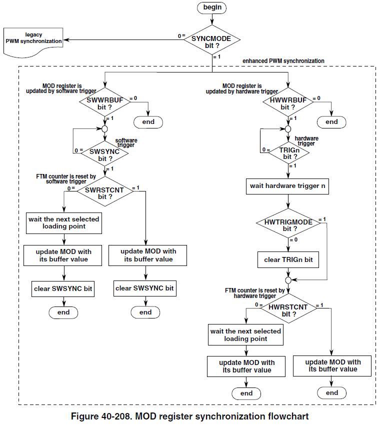
In the case of enhanced PWM synchronization, the MOD register synchronization depends on SWWRBUF, SWRSTCNT, HWWRBUF, and HWRSTCNT bits according to this flowchart:
When I want to start the sequence I load the init settings for the first 10us pulse and start the FTM:
void Start_FT0(void)
{
// Stop the FTM
FTM0_SC &= ~FTM_SC_CLKS_MASK; // Set clock source to "00" - therefore disabled.
// Clear all interrupt flags that might be set:
FTM0_C3SC &= ~FTM_CnSC_CHF_MASK;
// Load the channel timing values
FTM0_C2V = 4;
FTM0_C3V = 484; /*10us pulse*/
// Reset the FTM counter value to CNTIN
/* FTM0_CNT: COUNT=0 */
FTM0_CNT &= (uint32_t)~0xFFFFUL;
// Reset logic flag
IN_SECOND_STAGE = false;
// Start the FTM counter by setting the clock source to the system clock.
/* FTM0_SC: TOF=0,TOIE=0,CPWMS=0,CLKS=1,PS=0 */
FTM0_SC = (uint32_t)((FTM0_SC & (uint32_t)~0xF7UL) | (uint32_t)0x08UL);
}
..and my interrupt handler tries to load the new values when triggered by the falling edge of the first pulse (CH3 event):
if(FTM0_C3SC & FTM_CnSC_CHF_MASK)
{
// channel 3 interrupt
if(!IN_SECOND_STAGE)
{
const uint32_t endOfPulse = FTM0_C3V;
FTM0_C2V = endOfPulse + 480 /*10us gap*/;
FTM0_C3V = endOfPulse + 480 +(480*2) /* 20us pulse*/;
// Force Software Triggered Sync
FTM0_SYNC |= FTM_SYNC_SWSYNC_MASK;
IN_SECOND_STAGE = TRUE;
}
else
{
// End of SECOND pulse, stop the FTM.
FTM0_SC &= ~FTM_SC_CLKS_MASK; // Set clock source to "00" - therefore disabled.
IN_SECOND_STAGE=FALSE;
}
}
// Clear the interrupts
FTM0_C0SC &= ~FTM_CnSC_CHF_MASK;
FTM0_C1SC &= ~FTM_CnSC_CHF_MASK;
FTM0_C2SC &= ~FTM_CnSC_CHF_MASK;
FTM0_C3SC &= ~FTM_CnSC_CHF_MASK;
FTM0_C4SC &= ~FTM_CnSC_CHF_MASK;
FTM0_C5SC &= ~FTM_CnSC_CHF_MASK;
FTM0_C6SC &= ~FTM_CnSC_CHF_MASK;
FTM0_C7SC &= ~FTM_CnSC_CHF_MASK;The first pulse appears correctly at the pin, and the interrupt handler fires and the code is processed.
The line "FTM0_SYNC |= FTM_SYNC_SWSYNC_MASK;" sets the SWSYNC bit, and the manual indicates that once the sync has taken place that bit will get cleared... but it never does.
It never clears, and my second pulse never appears.
Following the left side of the flowchart down, the difference between an immediate update to the MOD register, and a delayed update (at the next loading point) is whether SWRSTCNT is set or not. I do NOT have this bit set, as the documentation indicates that this would cause the CNT register to reset to its start value, which is not what I want.
I am assuming that as what I want is the C(n)V (and C(n+1)V) registers to be updated but not the CNT value I set the SWWRBUF bit instead:

If I don't set the SWRSTCNT bit as well then it doesn't work, if I DO set the SWRSTCNT bit then the software trigger is handled immediately as expected, but the CNT value is also reset which is NOT wanted.
Is there some setting I have missed, or is it not possible to configure the K60 to update the CnV registers and not restart the CNT value?

 Hui_Ma
- Mark as New
- Bookmark
- Subscribe
- Mute
- Subscribe to RSS Feed
- Permalink
- Report Inappropriate Content
Hi,
Please refer below code about FlexTimer combine PWM synchronization:
void FTM_Sync_Trigger (void)
{
SIM_SCGC6 |= SIM_SCGC6_FTM0_MASK; /* Enable clock for FTM0 */
PORTC_PCR1 = (0|PORT_PCR_MUX(4)); /* FTM0_CH0 enable on PTC1 */
PORTC_PCR2 = (0|PORT_PCR_MUX(4)); /* FTM0_CH1 enable on PTC2 */
/* FTM0 init */
/* Configure FTM0CH0 and FTM0CH1 as PWM combineed operation for syncronization test*/
FTM0_MODE = 0x05; /* FTM features are enabled ans write protection is disabled */
FTM0_COMBINE = 0x23; /* Combine is enabled, Output CH0 and CH1 are complementary */
FTM0_C0SC = 0x28; /* High true PWM */
FTM0_C1SC = 0x28;
FTM0_MOD = 999; /* Initial value of FTM0 */
FTM0_CNTIN = 0;
FTM0_C0V = 100;
FTM0_C1V = 800;
FTM0_SC = 0x08; /*Start Timer,FTM CLOCK = BUSCLK /1 */
FTM0_SYNCONF = 0x00000034; //Legacy PWM synchronization is selected.
FTM0_SYNC = 0x03;
FTM0_C0V = 200;
FTM0_C1V = 400;
FTM0_SYNC = 0x83;
printf("Check the register value changed after synchronization\r\n");
/*
FTM0_C0V = 100;
FTM0_C1V = 800;
printf("Check the register still keep previous value before new synchronization\r\n");
printf("FTM0_C0V = %x\r\n",FTM0_C0V);
printf("FTM0_C1V = %x\r\n",FTM0_C1V);
FTM0_SYNC = 0x83;
printf("Check the register value changed after synchronization\r\n");
printf("FTM0_C0V = %x\r\n",FTM0_C0V);
printf("FTM0_C1V = %x\r\n",FTM0_C1V);
*/
}
Attached is example code to update CnV register for CPWM and Combine PWM mode.
Have a great day,
Ma Hui
-----------------------------------------------------------------------------------------------------------------------
Note: If this post answers your question, please click the Correct Answer button. Thank you!
-----------------------------------------------------------------------------------------------------------------------
