- Forums
- Product Forums
- General Purpose MicrocontrollersGeneral Purpose Microcontrollers
- i.MX Forumsi.MX Forums
- QorIQ Processing PlatformsQorIQ Processing Platforms
- Identification and SecurityIdentification and Security
- Power ManagementPower Management
- Wireless ConnectivityWireless Connectivity
- RFID / NFCRFID / NFC
- Advanced AnalogAdvanced Analog
- MCX Microcontrollers
- S32G
- S32K
- S32V
- MPC5xxx
- Other NXP Products
- S12 / MagniV Microcontrollers
- Powertrain and Electrification Analog Drivers
- Sensors
- Vybrid Processors
- Digital Signal Controllers
- 8-bit Microcontrollers
- ColdFire/68K Microcontrollers and Processors
- PowerQUICC Processors
- OSBDM and TBDML
- S32M
- S32Z/E
-
- Solution Forums
- Software Forums
- MCUXpresso Software and ToolsMCUXpresso Software and Tools
- CodeWarriorCodeWarrior
- MQX Software SolutionsMQX Software Solutions
- Model-Based Design Toolbox (MBDT)Model-Based Design Toolbox (MBDT)
- FreeMASTER
- eIQ Machine Learning Software
- Embedded Software and Tools Clinic
- S32 SDK
- S32 Design Studio
- GUI Guider
- Zephyr Project
- Voice Technology
- Application Software Packs
- Secure Provisioning SDK (SPSDK)
- Processor Expert Software
- Generative AI & LLMs
-
- Topics
- Mobile Robotics - Drones and RoversMobile Robotics - Drones and Rovers
- NXP Training ContentNXP Training Content
- University ProgramsUniversity Programs
- Rapid IoT
- NXP Designs
- SafeAssure-Community
- OSS Security & Maintenance
- Using Our Community
-
- Cloud Lab Forums
-
- Knowledge Bases
- ARM Microcontrollers
- i.MX Processors
- Identification and Security
- Model-Based Design Toolbox (MBDT)
- QorIQ Processing Platforms
- S32 Automotive Processing Platform
- Wireless Connectivity
- CodeWarrior
- MCUXpresso Suite of Software and Tools
- MQX Software Solutions
- RFID / NFC
- Advanced Analog
-
- NXP Tech Blogs
- Home
- :
- Wireless Connectivity
- :
- Wireless Connectivity Knowledge Base
- :
- Direct Test Mode (DTM) Configurations for the KW family
Direct Test Mode (DTM) Configurations for the KW family
- Subscribe to RSS Feed
- Mark as New
- Mark as Read
- Bookmark
- Subscribe
- Printer Friendly Page
- Report Inappropriate Content
Direct Test Mode (DTM) Configurations for the KW family
Direct Test Mode (DTM) Configurations for the KW family
Bluetooth® Low-Energy (BLE) RF PHY tests can be done by using the Direct Test Mode (DTM).
This document will help as a guide to perform the test using a device from the KW family.
Direct Test Mode
Direct Test Mode (DTM) is used to control the Device Under Test (DUT) and provides a report with the results from the tests performed by the Tester.
There are two ways to perform those tests:
- HCI
- Through a 2-wire UART interface
The packet format from the DTM is different from the HCI commands.
For further information of the commands and this type of tests, please refer to the Bluetooth Core Specifications, Vol 6, Part F: Direct Test Mode
Software
This guide will use the KW41Z as example, but the same changes must be applicable for the rest of the devices
- Download and install the software SDK of the device to use by following the getting started in the device page. In this case the SDK of the KW41Z will be downloaded from the MCUXpresso Builder.
Setup for DTM using HCI
- Import the hci_black_box example to the IDE according to the getting started of the device.
- Download and open the latest version of the Test Tool available in the page of the device under Lab & Test Software in the Software and Tools Tab.
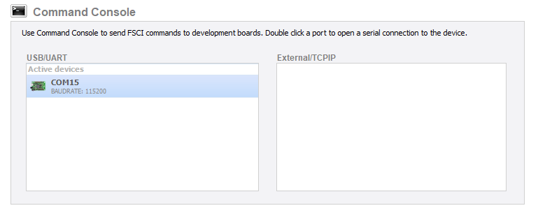
- Open the Command console of the board, please be sure that you have the correct baud rate set for the example (Default: 115200)
- Select one of the available commands to either start or finish tests
Setup for DTM using DTM pins
You can choose from any example available while making sure that the pins chosen for DTM are not occupied or used.
- Import the beacon example to the IDE according to the getting started of the device.
The DTM pins behave as a UART interface; in order to enable them in our KW devices there is the need to follow the next steps
- Look at the Reference manual of the device and locate the pins that support the DTM_TX and the DTM_RX. In this case, we will select the PTB1 and PTB2.
- Set the ALT_MUX of the pin in the code to work as DTM
PORT_SetPinMux(PORTB, PIN1_IDX, kPORT_MuxAlt2); /* PORTB1 (pin 17) is configured as DTM_RX */
PORT_SetPinMux(PORTB, PIN2_IDX, kPORT_MuxAlt3); /* PORTB2 (pin 18) is configured as DTM_TX */- Configure the baud rate of the DTM pins, this can be achieved by writing to the DTM_2WIRE_CONFIG register. This register is not available in the header file by default, so there is the need to create a pointer to such address. To verify this data, you can check the chapter 45.2.3.1.4 Test and Debug Registers Descriptions for the Bluetooth Link Layer of the reference manual.
#define DTM_2WIRE_CONFIG 0x580
#define BTLE_RF_DTM_2WIRE_CONFIG (*(volatile uint16_t *) (BTLE_RF_BASE+DTM_2WIRE_CONFIG))
BTLE_RF_DTM_2WIRE_CONFIG = 0x0042; /*Configure DTM pins baud rate of 115200*/


